Tag Archives: nasa

Where is Blackbird NASA 831? And the problems with the old Testors kit.

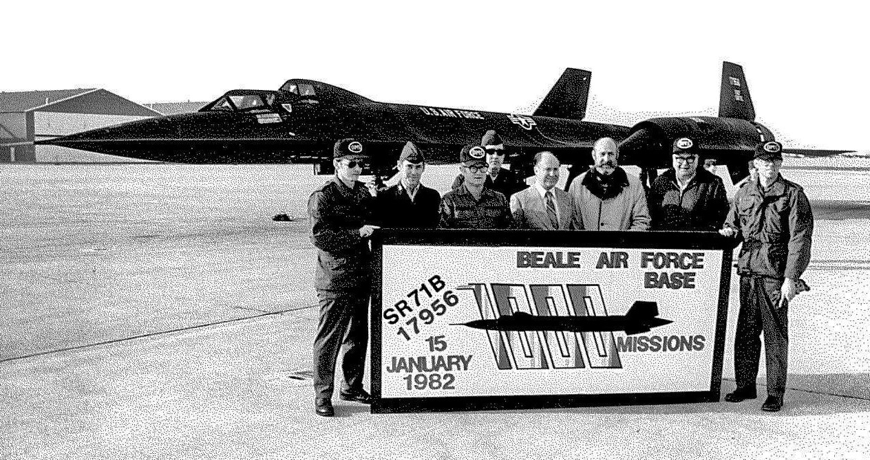
The SR-71B that would become NASA 831. U.S. Air Force photo by Airman Luis Ruiz-Vazquez, 15JAN1982.

SR-71B #61-7956, on the day of its delivery to NASA, 24JUL1991.

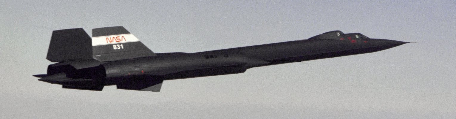
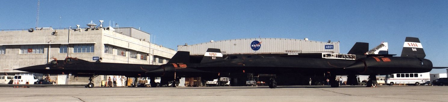
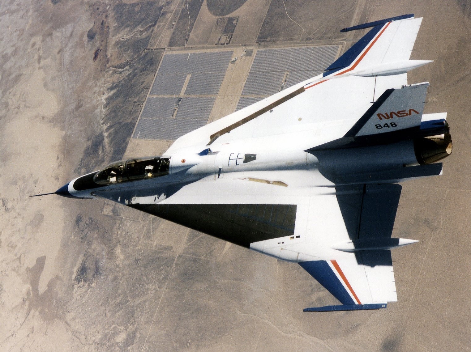
NASA photo of SR-71B #831, July 1991.
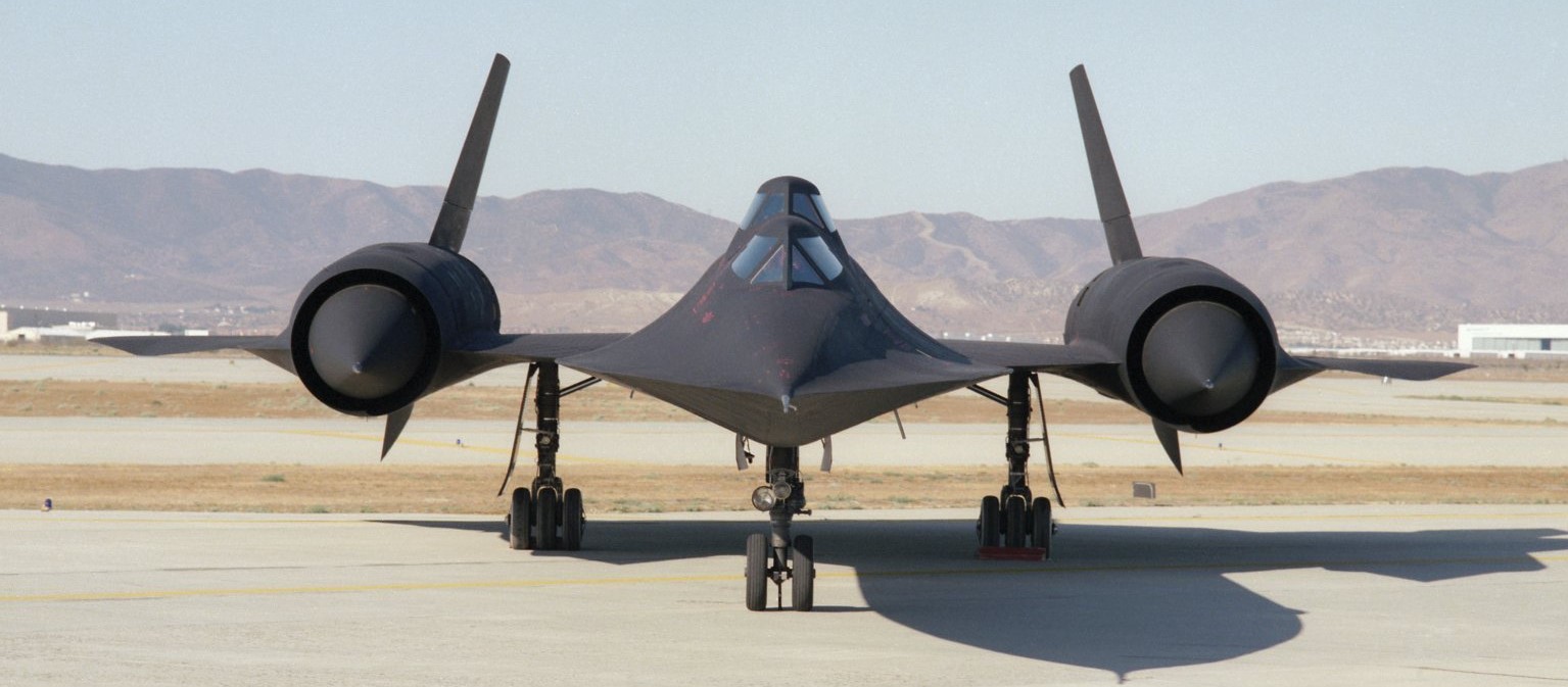
The ‘B’ version of the Blackbird has ventral fins on the nacelles, like the YF-12A.

Silent take-off video from 1991:

In July 1991, NASA began using the last of two SR-71B trainers (the other SR-71B was lost in a crash in 1968), #61-7956, also known as NASA 831.

Silent refueling video from 1991:

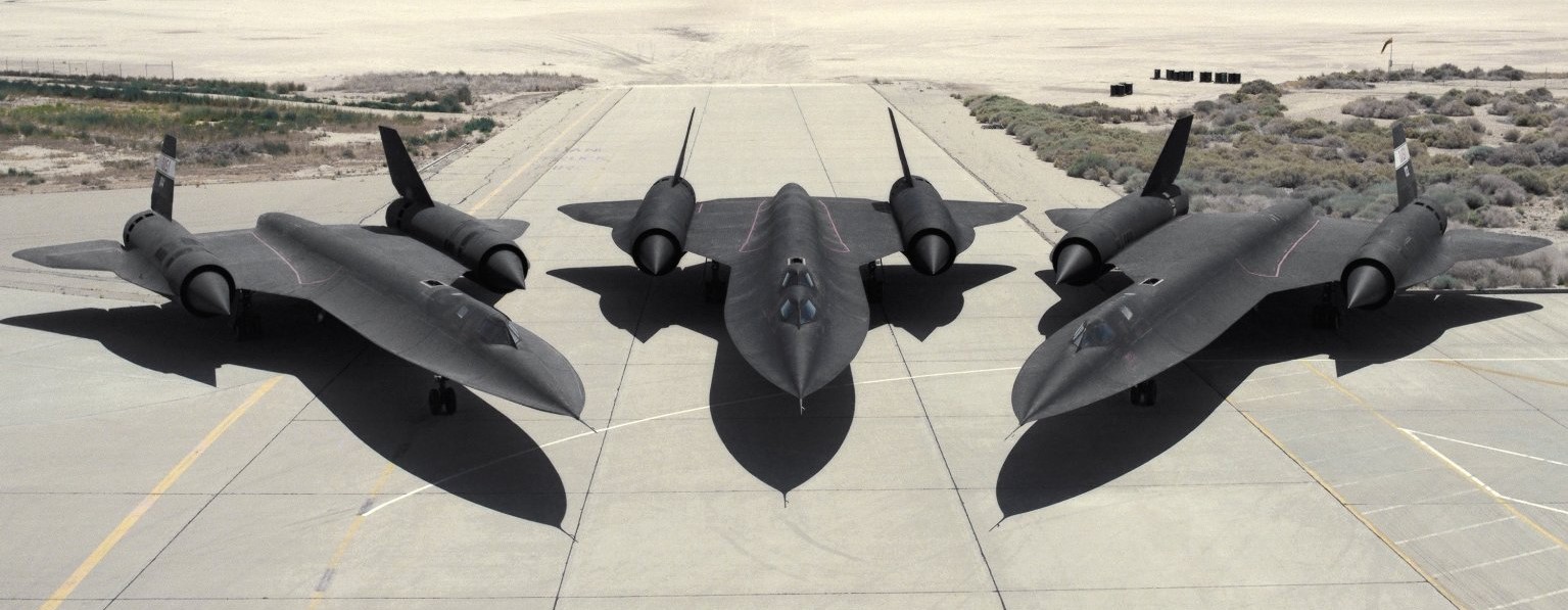
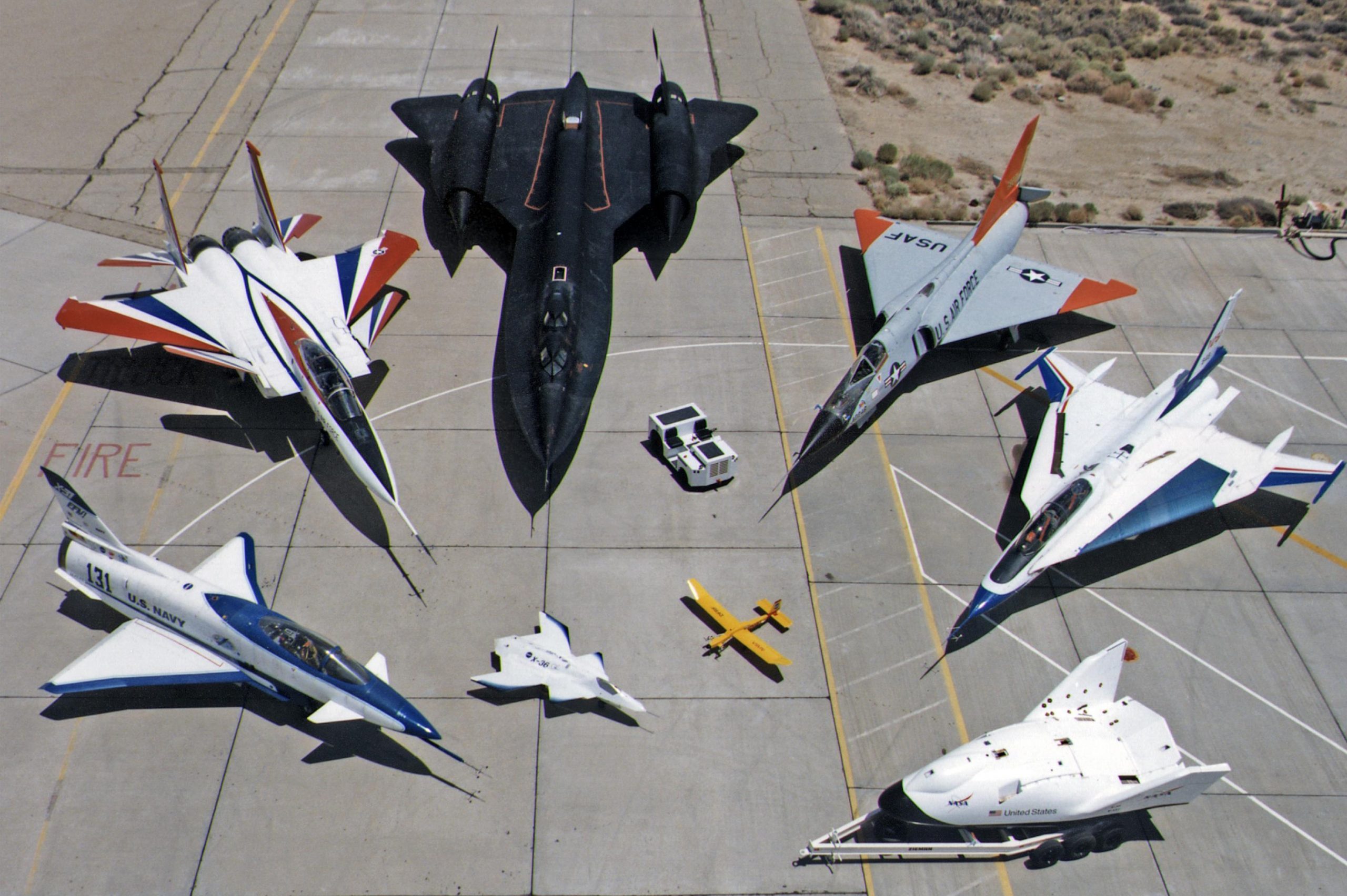
NASA photo from 1992, showing-off the three SR-71s they got ‘on loan’ from the U.S. Air Force. NASA 831 is in the middle.

Silent take-off video from 1992:

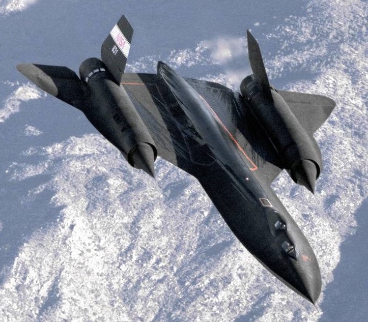
SR-71B ‘831’, photo via NASA, 1994.

NASA photo of 831, March 1996.

831 was used for crew training and various research programs on Dryden Flight Research Center (now called Armstrong Flight Research Center, on Edwards Air Force Base), California, until October 1997.

This NASA photo was made in July 1997, just a few months before 831 was retired.

NASA photo from August 1997, in the foreground is SR-71A carrying the Linear Aerospike experiment, behind it is retiring SR-71B 831.

Same photo but I zoomed in to show the apparatus on the canopies of 831.

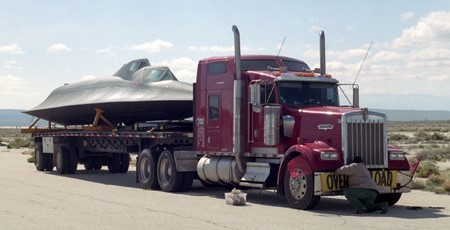
At the end of 2002, pieces and parts of NASA 831 were loaded onto tractor-trailers at Edwards AFB (Dryden Research Center), California, for the trip to Michigan. Photo via NASA.

In March 2003, NASA 831 went on display at the Kalamazoo Aviation History Museum in Kalamazoo, Michigan.  Some very detailed walk-around photos of its arrival, in pieces, can be seen at SR-71.org, as well as a history of the reconstruction at the museum.

In 2015 (and updated in 2017), for some reason NASA claims 831 went on display at the Pima Air and Space Museum in Tucson, Arizona.  However, a check of the Pima Air and Space website reveals it is an SR-71A, not the B version.

To confuse things even more, some aviation blogs claim the Evergreen Aviation & Space Museum in McMinnville, Oregon, has NASA 831!  The museum’s own SR-71 FAQ section states they’ve had the SR-71 since 2002! They post three photos; two are NASA photos, with one being of 831, and the other being an SR-71A being configured for the Linear Aerospike experiment.  The third photo is of the museum’s SR-71 and it is clearly an SR-71A, not the B or even 831.

At this point, the Kalamazoo Aviation History Museum is the only location that has photographic proof that they have NASA 831.  Not only does their website have lots of detailed photos of NASA 831, but they got lots of photos of other Blackbirds.

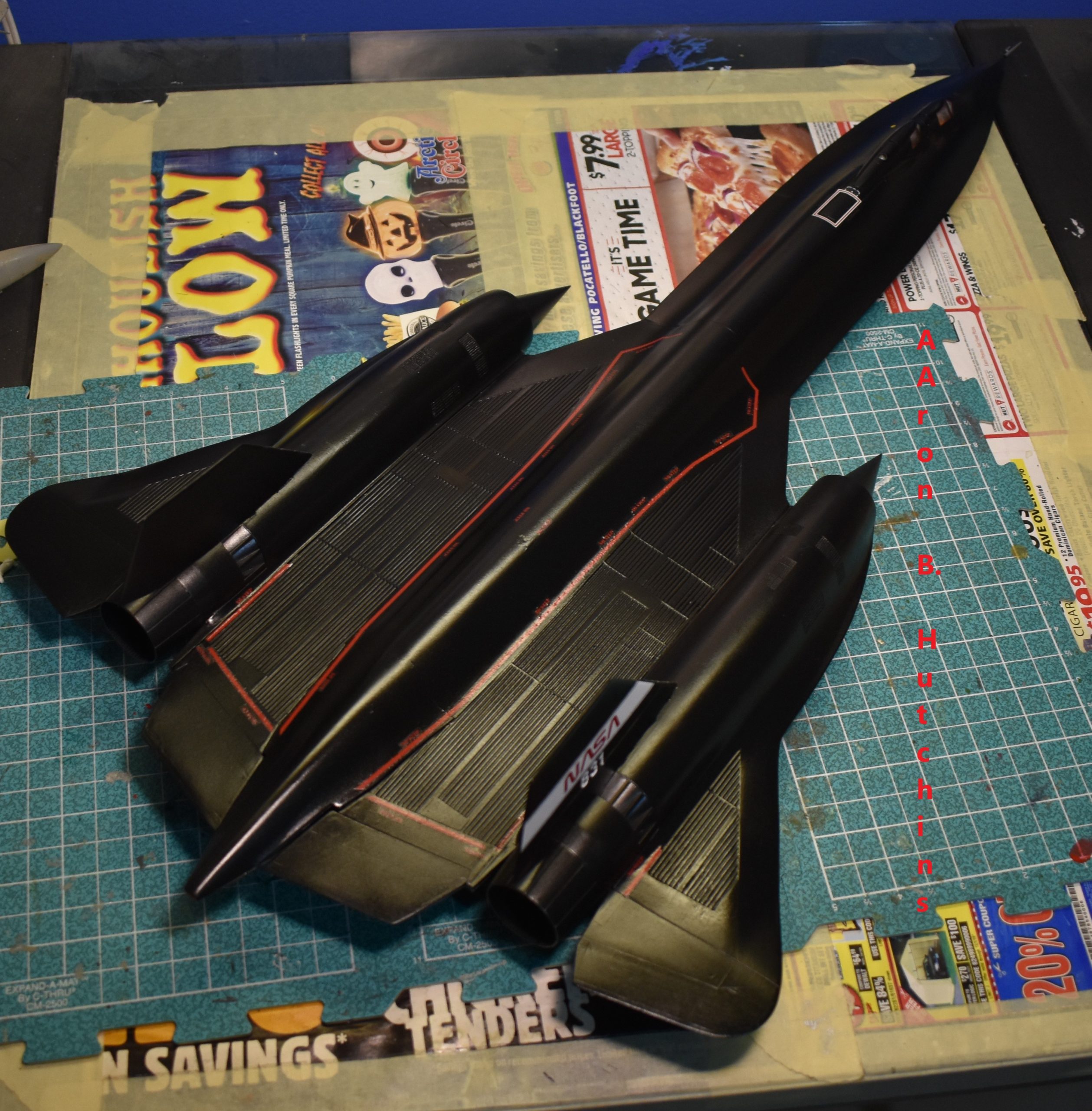
Testors SR-71 built as the ‘B’ version, NASA 831. I had to scratch build an aerial refueling door as Testors did not provide it.

After 25 years in my stash-pile, and realizing that the outrageous prices being fetched for an old Testors SR-71 might be due to Testors ceasing to exist, and the fact that the new Revell-Germany SR-71 does not include parts for the ‘B’ version, I decided it was time to build it.

NASA photo, July 1995.

The first problem I came across with the kit itself, was that Testors molded the refueling door in the open position and did not provide a door for the closed position, I wanted it closed so I had to use plastic sheet to cover the open fuel receptacle.  Perhaps Testors got confused, photos of parked SR-71s do show the refueling door open, but that is because the hydraulics have relaxed, in-flight the door is closed, except when refueling.

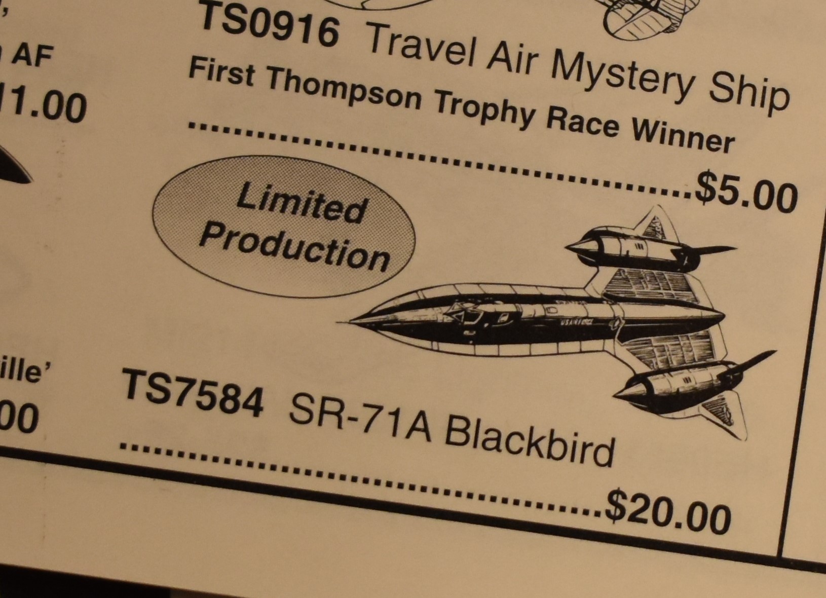
I still have a mail-order catalog showing the MSRP of $20 back in 1996-97. I realized that the kit was not promoted as being able to build the B version.

I bought the Testors kit back in 1997, when it was a whopping $20 brand new, and I got it on discount for less than $19!

Unfortunately, the box and decals didn’t survive the test of time; the outer end opening box literally began disintegrating, and the decals were cracked beyond use (I tried, even with a coat of clear they shattered in the water), I ended up getting some Caracal-Cartograf decals.

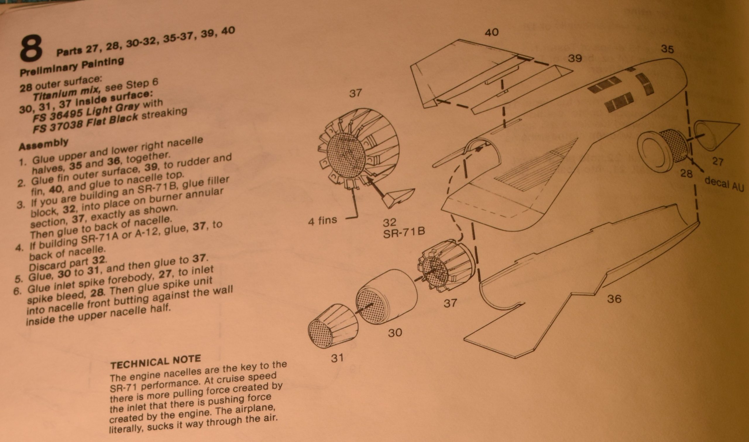
If you follow the order of assembly you will have problems.

I learned that if you follow the instructions and attach the rudders to the nacelles first, you will have problems attaching the afterburners.  Attach the afterburners before attaching the rudders.  I glued the intake spike (shock cone) behind the mounting point as I was building it to represent being in-flight.  The shock-cone retracts into the nacelle allowing the Blackbird to fly faster.

Dry fitting reveals a major problem.

Another problem is that the mounting holes in the center section are too small to allow the nacelles to fit.  Even after hollowing them out, and thinning the posts on the nacelles, I still ended up with stress cracks on the center section.

Even after surgery to make the parts fit, stress cracks appeared.

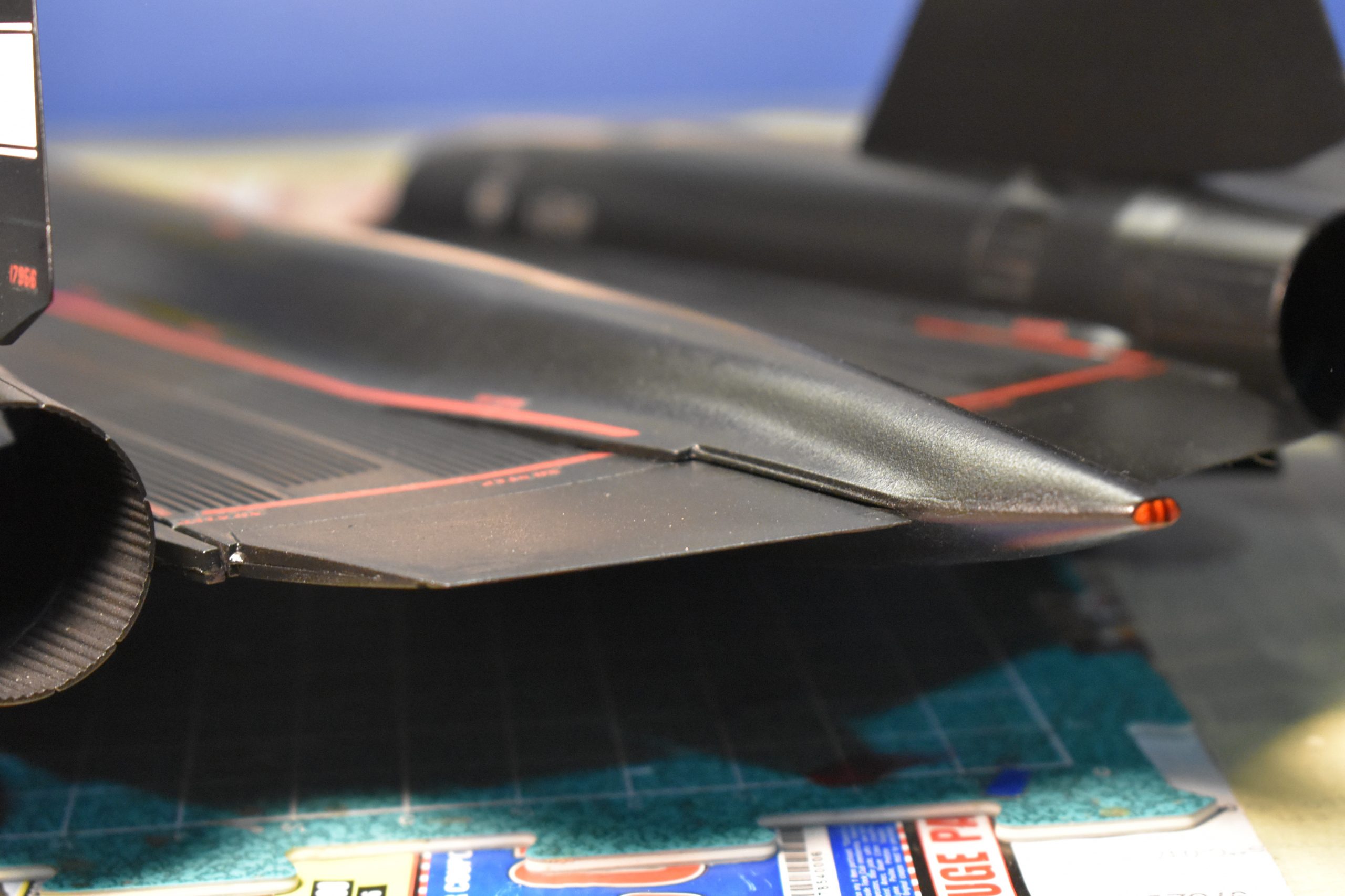
Lack of mounting stubs caused the rear part of the wing to droop. Testors does not replicate the fuel dump, I tried by filing the pointy end flat and using paint.

For some reason Testors did not model the prominent fuel dump at the back of the Blackbird.  I decided to flatten the pointy end and then use red paint to represent the fuel dump.  Most photos of  the rear-end of SR-71s show the inside of the fuel dump was painted red.

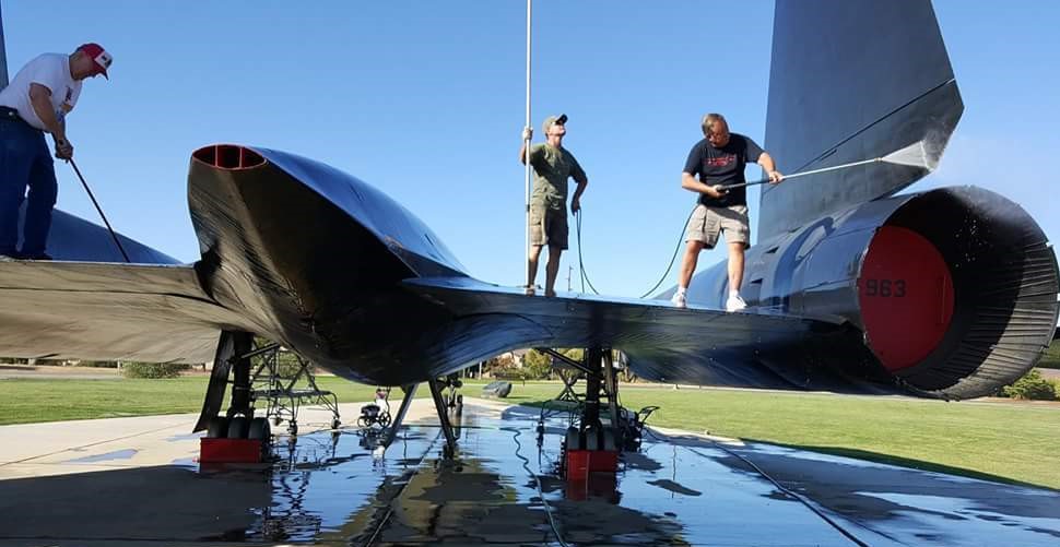
An SR-71 gate-guard on Beale AFB, California, showing the red painted fuel dump. USAF photo, 26JAN2016.

The kit does not come with pilots, using putty I modified some old Monogram pilots to look like astronauts, but then discovered the seats wouldn’t allow them to fit.  I had to chop off the pilot’s feet, butts and part of their backs to get them to fit.

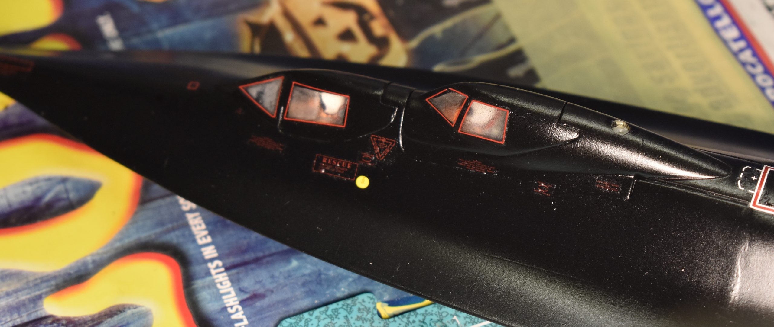
I modified some spare Monogram pilots. Turns out the red borders around the canopy glazing are incorrect, and the clear I used to get them to stay down fogged the canopies.

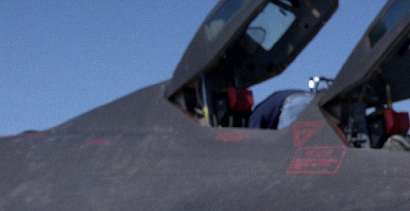
Forget those red canopy border decals, they are flat wrong.  While reviewing photos (unfortunately after I applied the decals) I noticed there are no red borders.  At certain angles it might look like there are, but the red that is sometimes seen around the glazing is actually the seals inside the canopy framing.

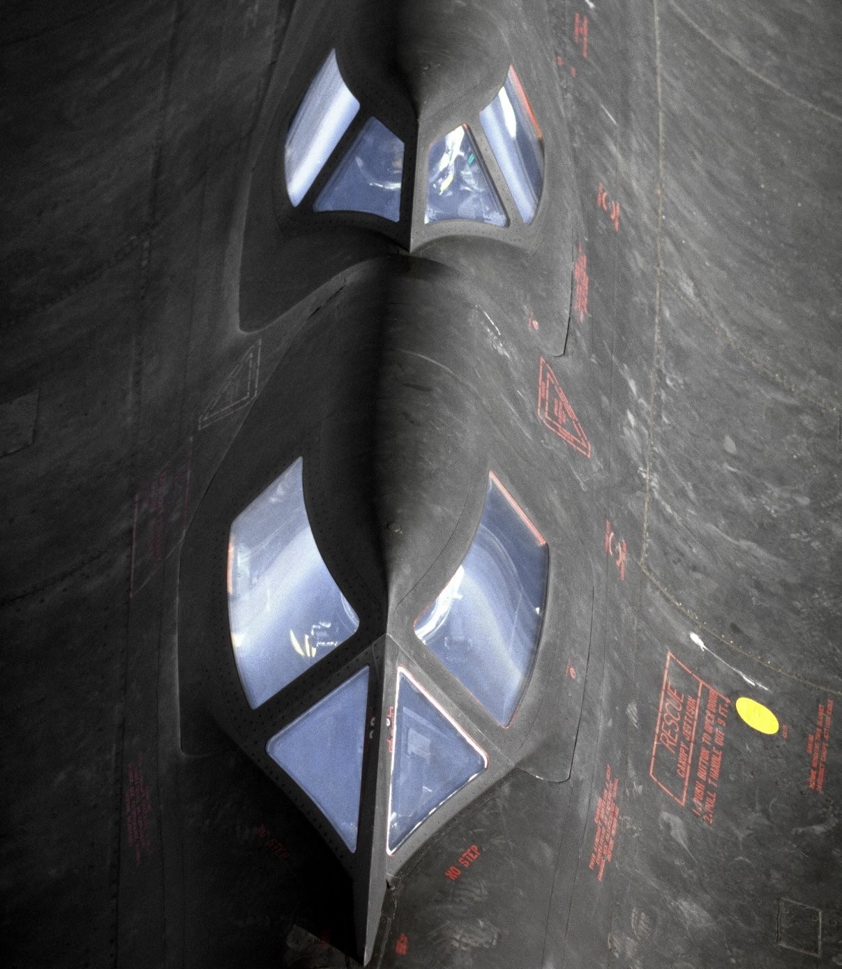
In this close-up of NASA SR-71B 831, you can see there are no red borders around the canopies. What is red are the seals inside the canopy framing. NASA photo, December 1994.

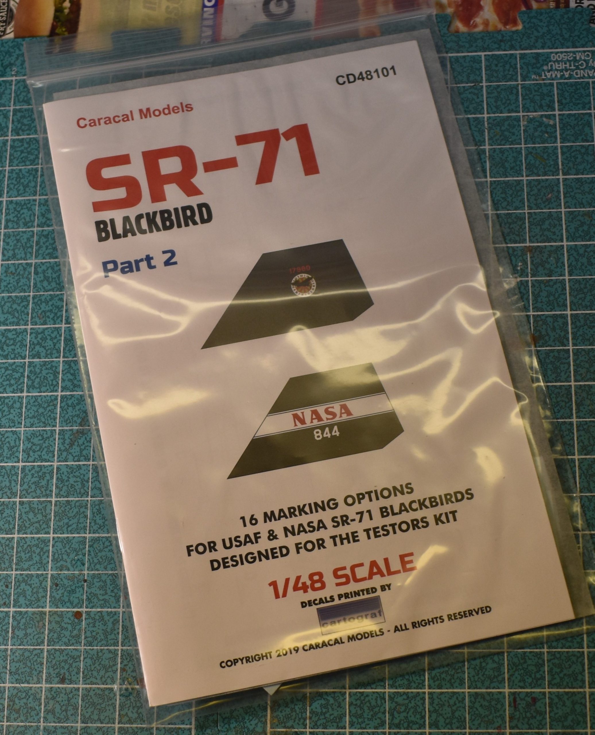
It was in the Caracal-Cartograf Blackbird Part-2 decal set that I discovered the markings for NASA 831.

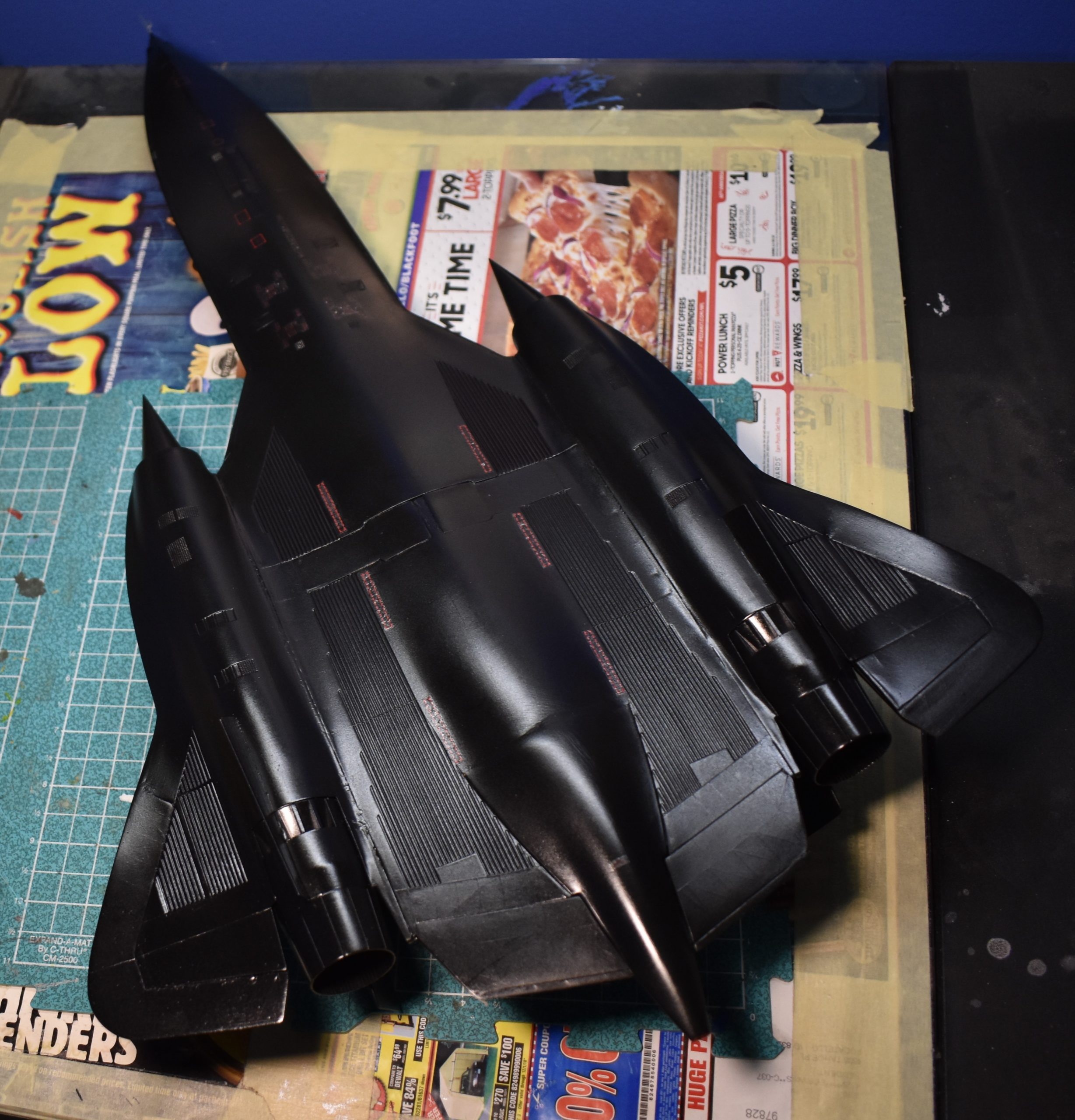
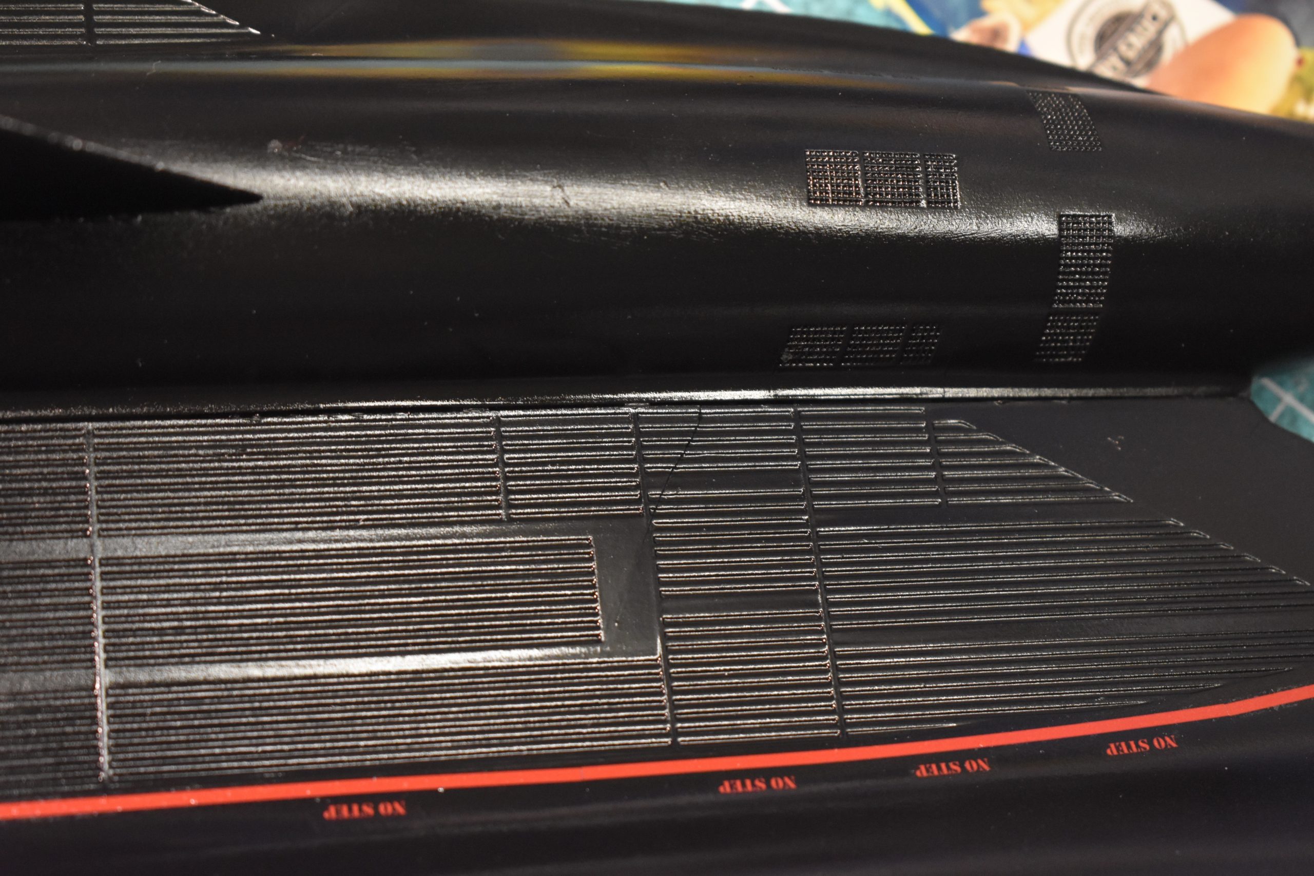
You might not can see, but even a coat of clear paint failed to force the aftermarket decals to lay flat on the underside of the Blackbird.

Even expensive (almost as much as what I paid for the Testors kit back in 1997) aftermarket decals can be wrong (like the red canopy borders), and not cooperate.  For some reason not known to me, the decals would not settle down on the underside of the kit.  Decal solution failed to keep the decals from wrinkling.  I applied clear paint and the result was no more wrinkles, instead I got blisters which hardened when the paint dried.

NASA photo of 831, sometime in 1995.

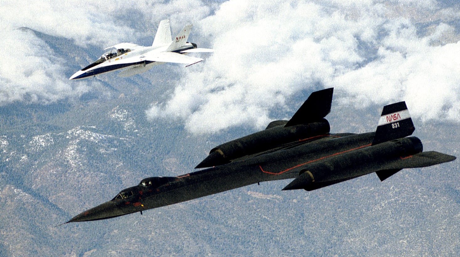
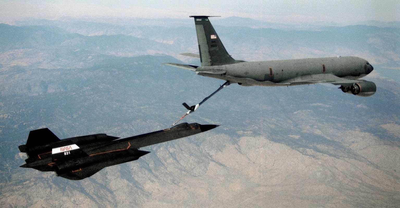
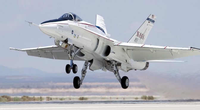
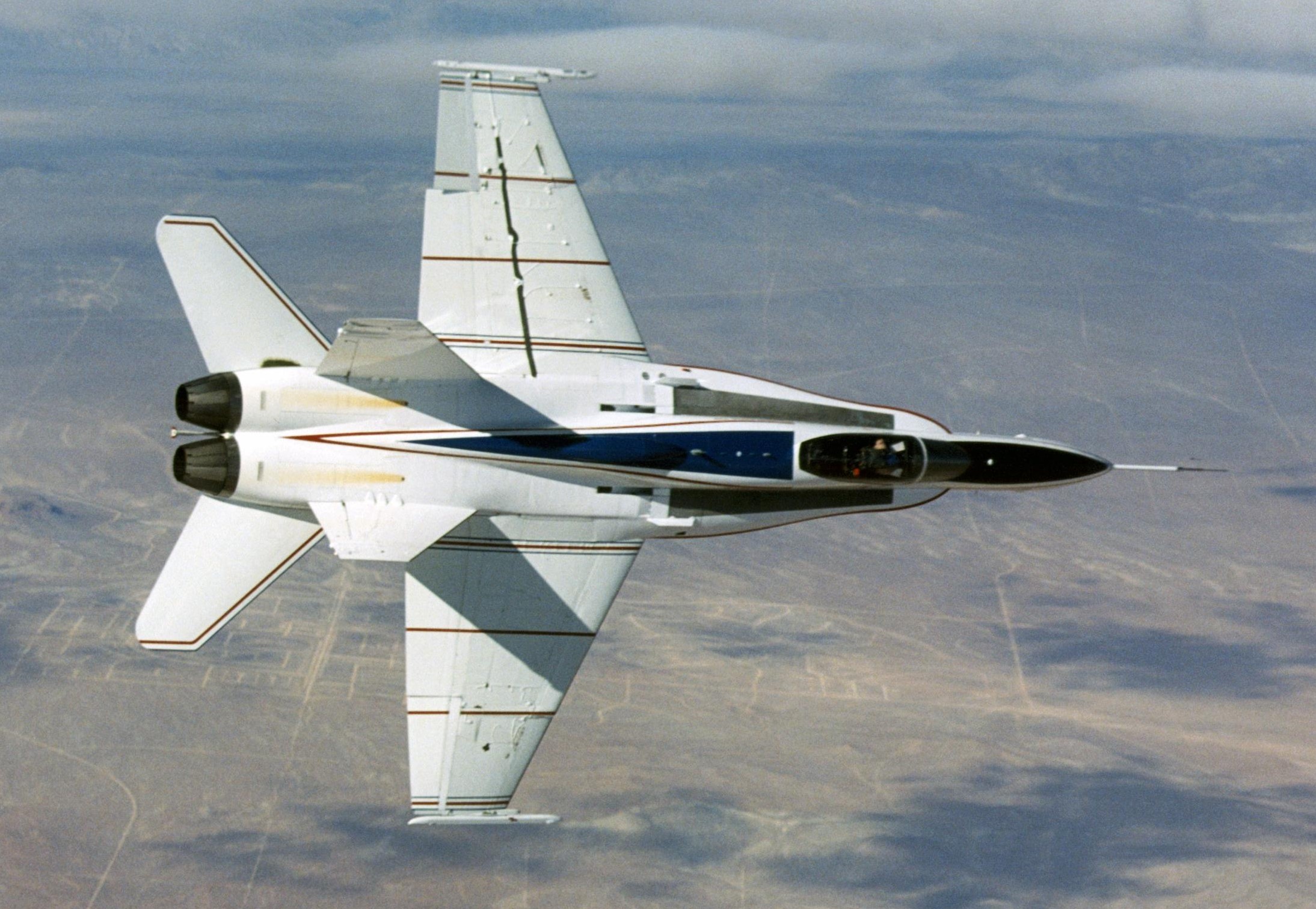
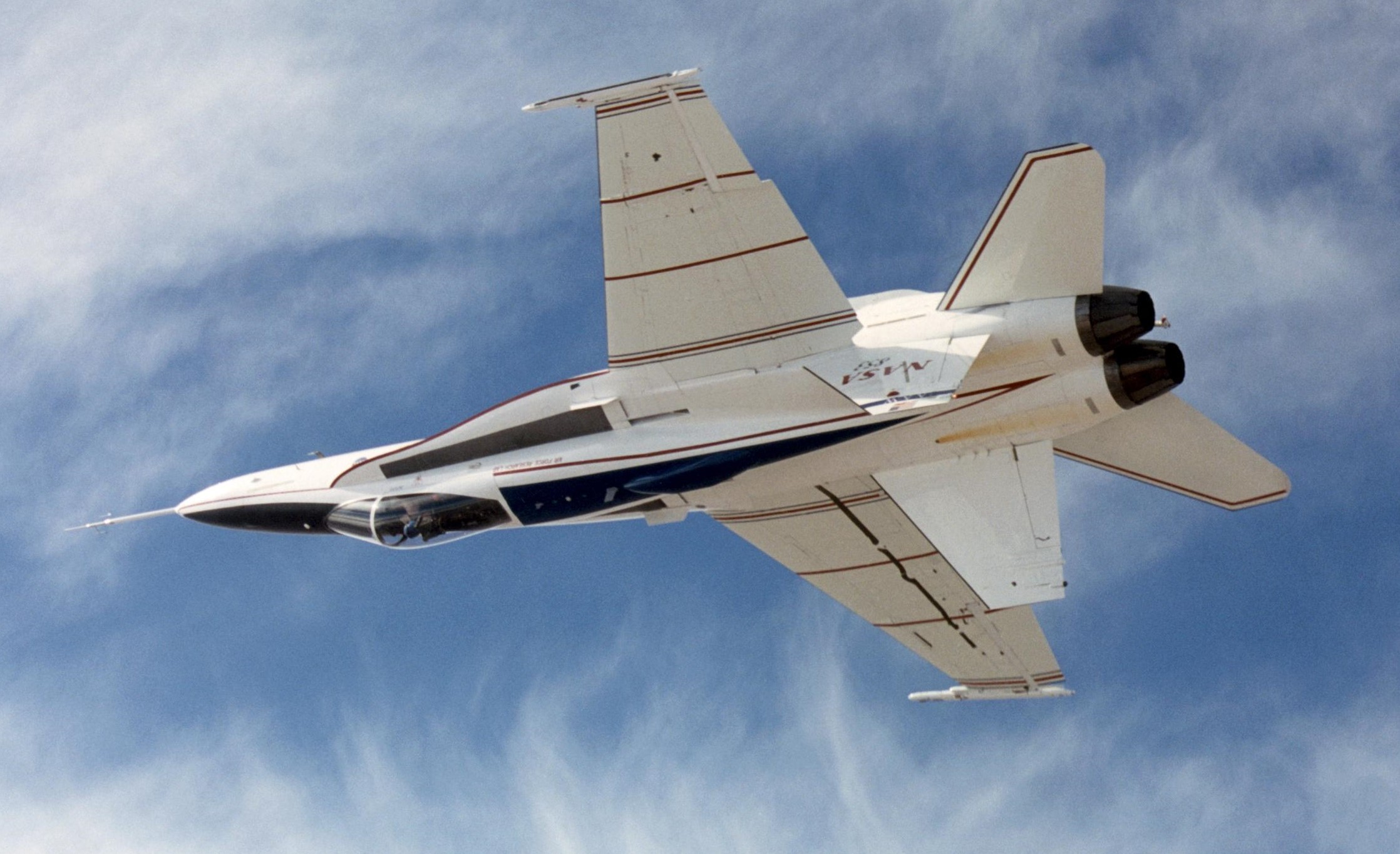
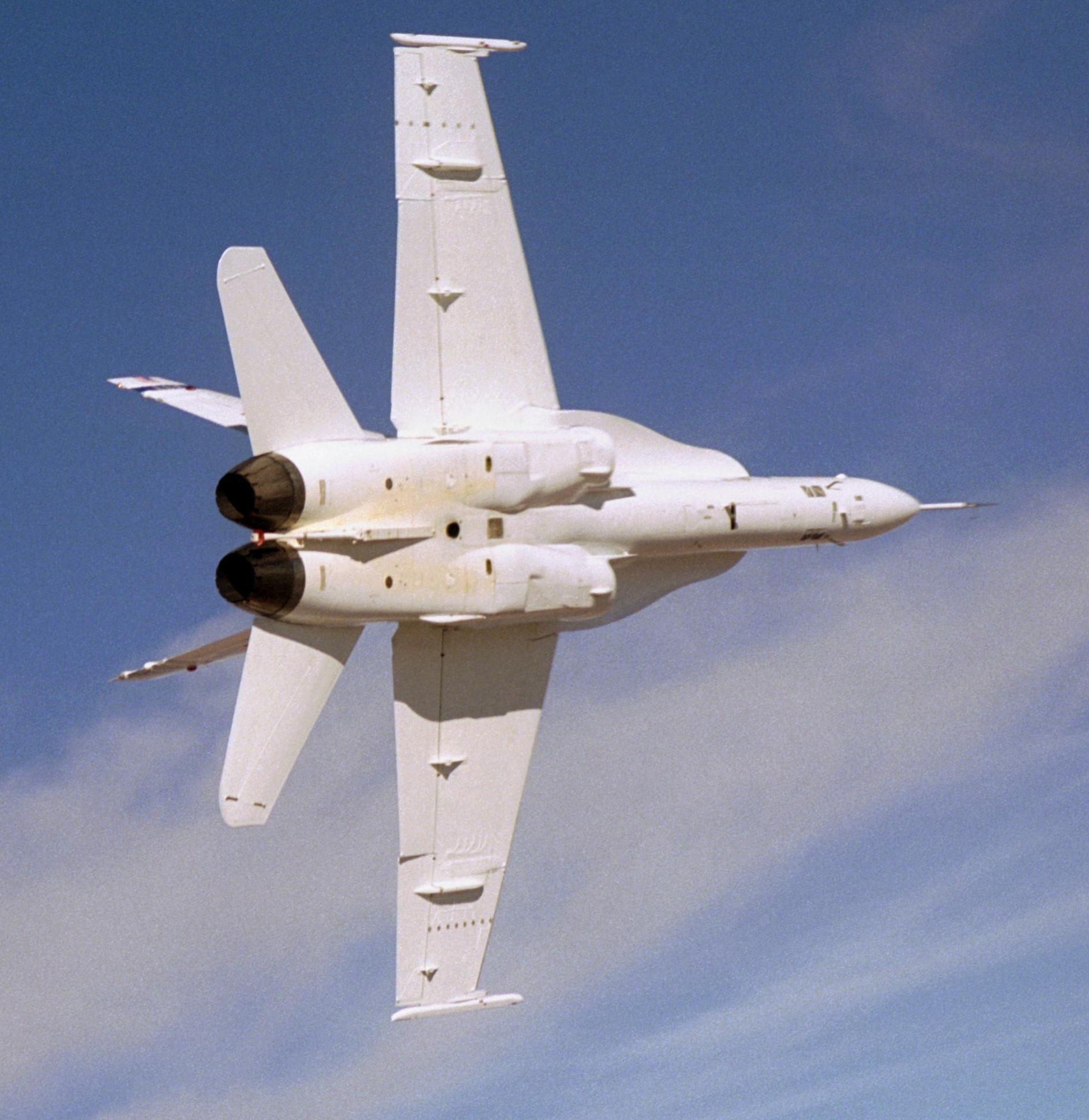
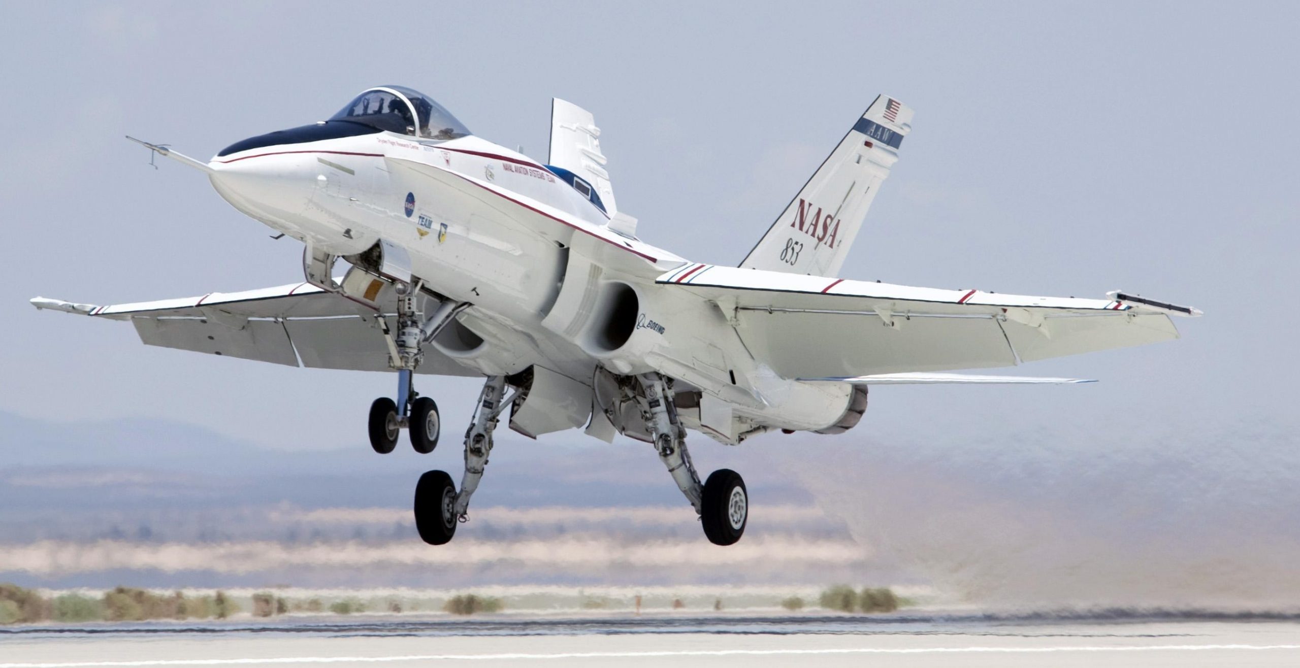
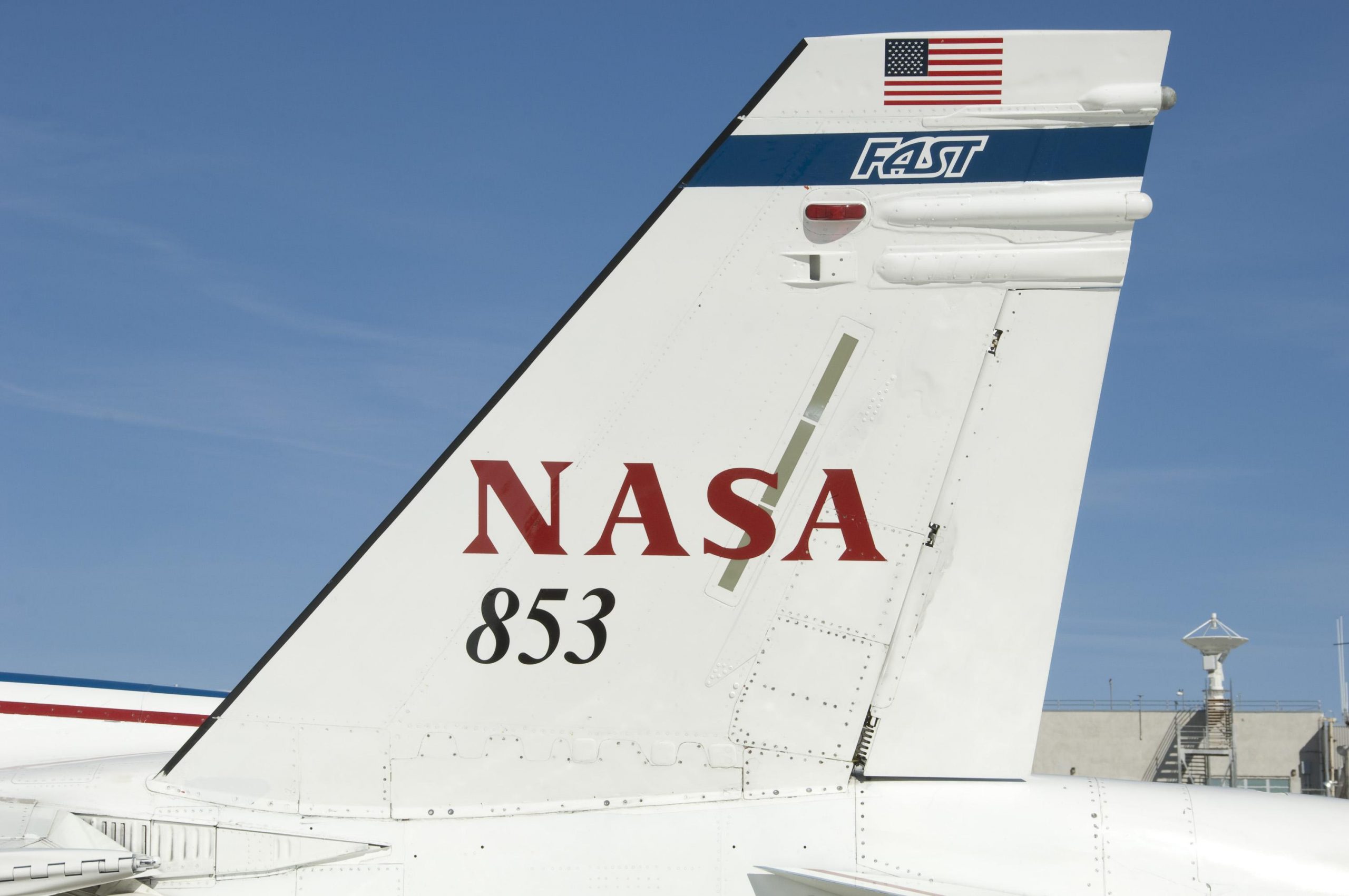
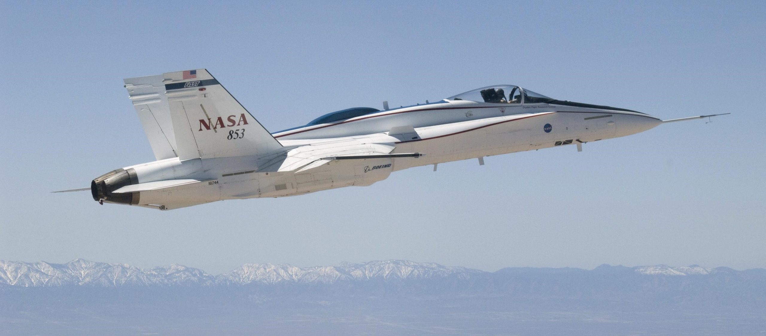
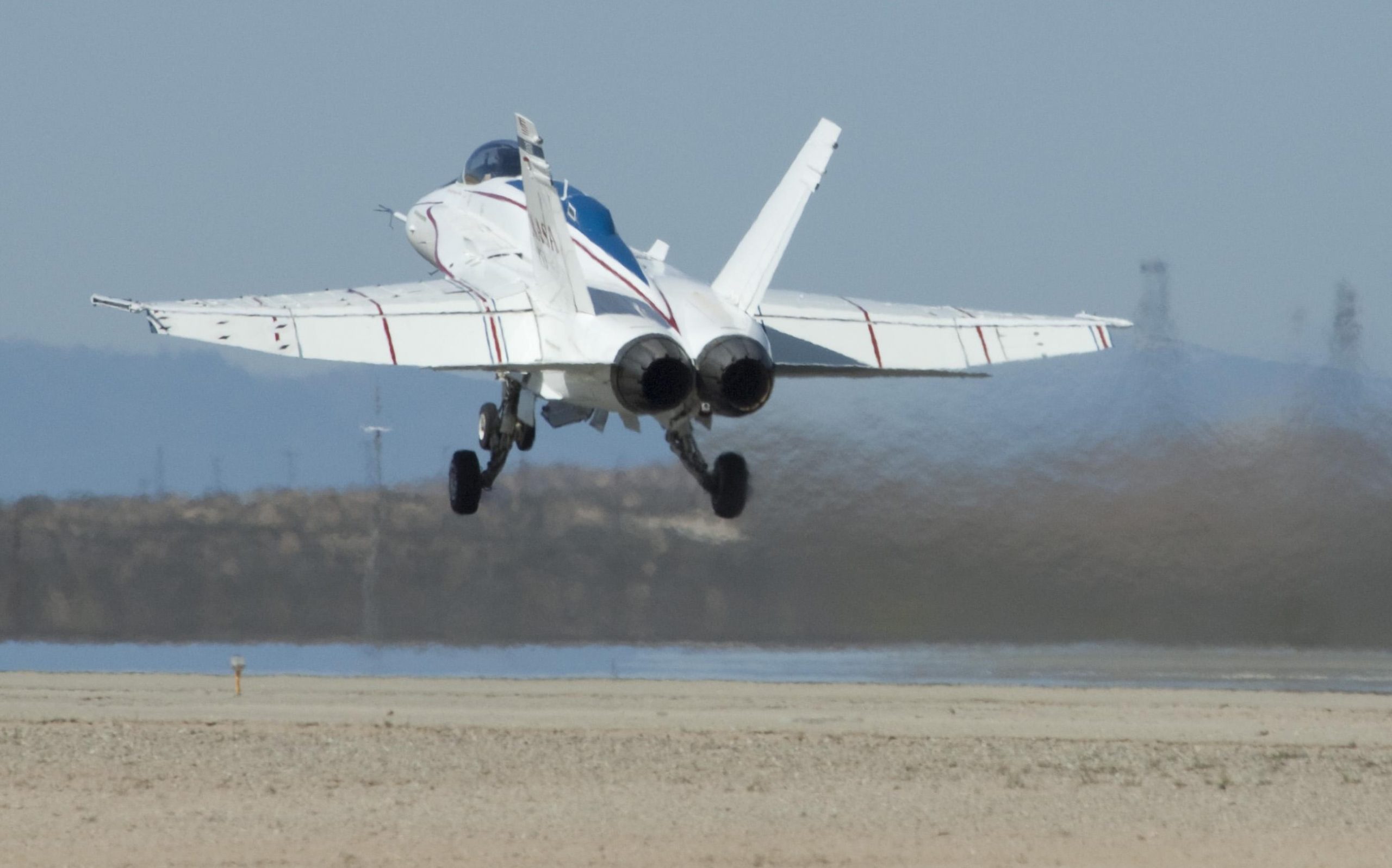
831 cruises over the Mojave Desert with a NASA F/A-18 Hornet flying safety chase. NASA photo sometime in 1996.

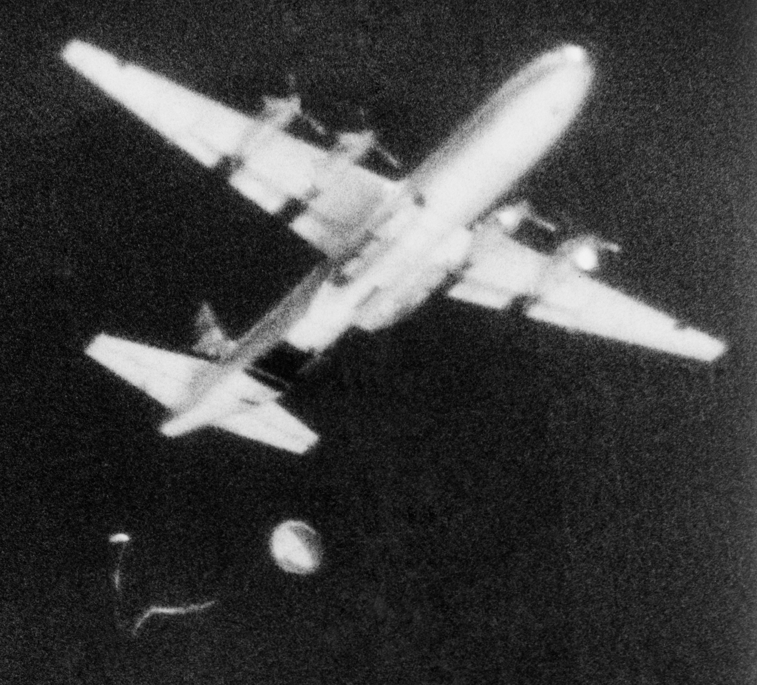
F-15 Eagle 50th Anniversary: 
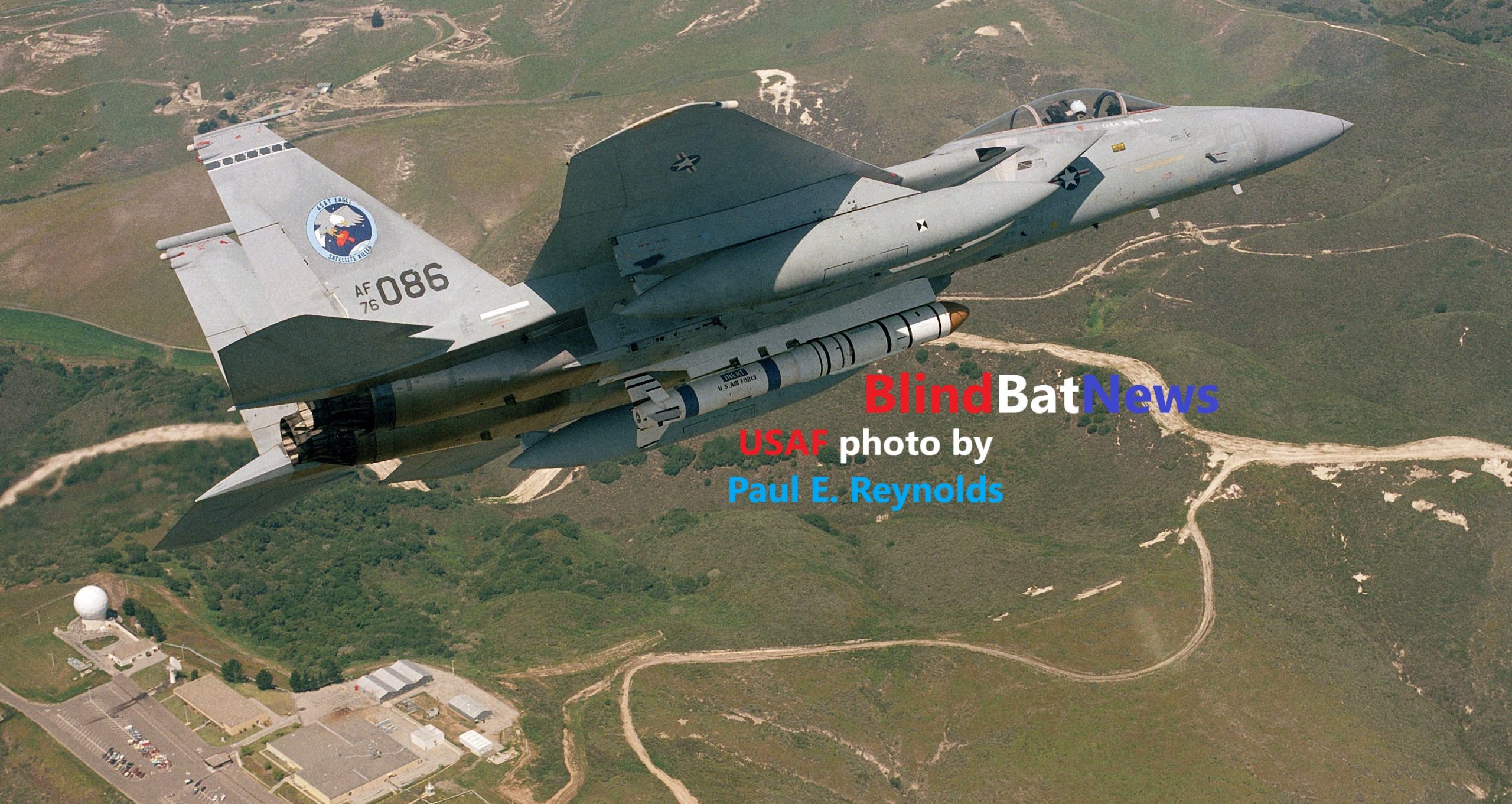
THE A-SAT, WITH SOME VISUAL TIPS FOR THE KIT BUILDER

Cold War Boats: 
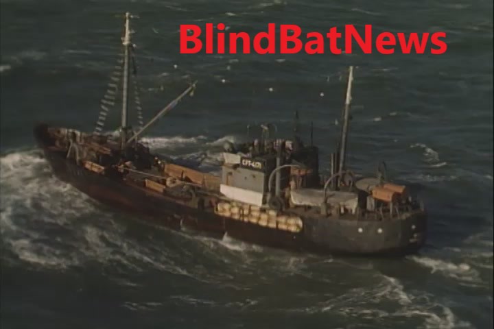
REVELL’S SPY TRAWLER IS FOR REALS! OR, WHO TOLD THE SOVIETS ABOUT EXERCISE TEAMWORK?

NACA’s ramjet F-82 Twin Mustang, 1949 crash & burn? Reborn more than 60 years later!

National Advisory Committee for Aeronautics (NACA) acquired three F-82E (P-82E) Twin Mustangs between 1947 and 1950.

NACA photo, 01APR1949.

The first F-82E (PQ-887) was used to test ramjet missiles over NACA Lewis Flight Propulsion Laboratory (now called NASA Glenn Research Center).

NACA photo, 1948.

With the creation of the U.S. Air Force in September 1947, the ‘P’ for pursuit was dropped for ‘F’ for fighter, and PQ-887 became FQ-887.

NACA photo, 1948.

The info that came with this photo says the ramjet tests took place over Wallops Island (Wallops Flight Facility), Virginia. NACA photo, 1948.

A 28MAY1951 Aviation Week article revealed the once secret Wallops Island operations, but stated that the ramjet craft were scale models of bigger things to come.

U.S. Army Air Force photo, XP-82 44-83887, 1945.

By April 1949, FQ-887 became XFQ-887, and a NACA press release claimed the ‘X’ represented that this F-82E was actually one of the two North American prototype XP-82s (#44-83887)!

Skidded off the paved runway, and down into the mud. NACA photo, 14DEC1949.

XFQ-887 then suffered a ‘runway incident’ in December 1949 and was ‘transferred’ after that.

NACA photo, 14DEC1949.

NACA photo, 14DEC1949.

Jacked-up out of the mud. NACA photo, 14DEC1949.

In 1950 two more F-82E came onboard. By the end of 1951, a new designed F-4 ramjet missile was tried-out.

NACA photo, 01DEC1951.

NACA photo, 01DEC1951.

The new F-4 ramjet missile was mounted in the center of the aircraft, instead of on the outboard wings.

NACA photo, 01DEC1951.

NACA photo, 1951.

NACA photo, 01DEC1951.

NACA photo, 1952.

NACA photo, 1952.

NACA photo, 1952.

Compare to wing mounted ramjet missile.

NACA photo, 1953.

Interestingly, these air-launched ramjet missiles look like the successful surface-to-air RIM-8 Talos missile used by the U.S. Navy, but with much fewer fins. The Talos ramjet project began in 1944, with its first flight in February 1945.

What happened to XFQ-887?  It was removed from military records in 1950, then ended up in the hands of an aircraft collector in Ohio, from 1965 to 1985.  It rotted away in a junkyard until 2008, when Brooks Aviation got a hold of it, restoration work began the same year, airworthiness was certified in 2011 even though the left fuselage still needed restoration. In 2019, XFQ-887 (XP-82) made its debut at the Fun-n-Sun Air Show in Florida.

https://www.facebook.com/169791783063916/videos/1815465248496553/

See and read a whole lot more about the return of XFQ-887 (XP-82) at XP-82 Twin Mustang Project.

Crash Landings:

USAAF photo.

USAAF P-51 MUSTANGS, ENGLAND, 1944-45

TRIPLE ENGINED F-106B DELTA DART; MORE TAXPAYER FUNDED SUPPORT FOR THE AIRLINER INDUSTRY

SALVAGING F4U CORSAIRS

NASA’s twisty-bendy F/A-18A

The Active Aeroelastic Wing (AAW) program (aka Boeing Phantom Works X-53) sought to determine the advantages of twisting flexible wings for primary maneuvering roll control at transonic and supersonic speeds, with traditional control surfaces such as ailerons and leading-edge flaps used to aerodynamically induce the twist. The idea is to design lighter, more flexible high aspect-ratio wings for future high-performance aircraft, which could translate to more economical operation or greater payload capability.

NASA photo, February 2003.

Active Aeroelastic Wing (AAW) F/A-18A (acquired in 1999 from the U.S. Navy) undergoes wing torsion testing at NASA’s Flight Loads Laboratory, Edwards Air Force Base, March-April 2001.

NASA photo, March 2001.

NASA Photo by Tom Tschida, April 2001.

Official NASA video:

NASA says the AAW program actually began in 1996, on paper.  Wings from NASA’s retired F/A-18 #840, formerly used in the High-Alpha Research Vehicle (HARV) project, were modified and installed on #853.

NASA photo, October 2001.

New paint-job, October 2001.

NASA photo by Tony Landis, 24OCT2001.

NASA Photo by Tom Tschida, 21MAR2002.

Before the official public unveiling, Centennial of Flight Commission decals were place on both sides of AAW 853, below the aft portion of the cockpit.  NASA says the AAW program was influenced by the fact that the Wright Brothers twisted the wings of their Wright Flyer to get it to turn.

NASA Photo by Tom Tschida, 21MAR2002.

NASA photo by Tony Landis, 27MAR2002.

In March 2002, NASA officially unveiled the modified AAW F/A-18A.

NASA Photo by Tom Tschida, 21MAR2002.

NASA photo, August 2002.

More wing torsion/vibration testing, August 2002.

NASA photo, August 2002.

NASA Photo by Tom Tschida, 22AUG2002.

15NOV2002, NASA photo by Tony Landis.

First flight of AAW F/A-18A #853 was 15NOV2002.

NASA photo by Carla Thomas, 15NOV2002.

During early flights it was determined that some of the original F/A-18 wings panels were too flexible at high speeds to create the desired roll rate.  The leading edge flap was divided into individually controlled sections, which seemed to solve the problem.

07FEB2003, NASA photo by Jim Ross.

February 2003.

07FEB2003, NASA photo by Jim Ross.

25JUN2003, NASA photo by Jim Ross.

Chased by another NASA F/A-18A, June 2003.

Official NASA video, 2003:

NASA photo, December 2004.

Flying over the U.S. Borax mine, near the Rogers Dry Lake, December 2004.

15DEC2004, NASA photo by Carla Thomas.

Official NASA video:

Official NASA video, March 2005:

The AAW program was officially completed in 2005.  The total cost of the AAW testing is estimated at $45-million.

NASA photo by Tony Landis, 18JUN2009.

In June 2009, the AAW #853 got a new lease on life, replacing an older NF-15B Integrated Resilient Aircraft Controls (IRAC) test aircraft, becoming the IRAC F/A-18A.

06APR2010, NASA photo by Tony Landis.

By April 2010, the tail flash/stripe was changed from reading AAW, to FAST (Full-scale Advanced Systems Testbed).

Official NASA video, 853 first flight as IRAC, April 2010:

06APR2010, NASA photo by Tony Landis.

06APR2010, NASA photo by Tony Landis.

One of the side benefits of aircraft testing is the creation of new computer systems which can be applied to other aircraft, military and civilian.

06APR2010, NASA photo by Tony Landis.

NASA VIKING, NO NOT THE MARS LANDERS! OR, LAST FLIGHT OF A VIKING.

F-16XL LAMINAR FLOW, ONCE AGAIN NASA (TAXPAYERS) SAVING THE ‘PRIVATE SECTOR’ AIRLINER INDUSTRY!

NASA’S 737, TEST-BED FOR THE CIVILIAN AIRLINER INDUSTRY!

NASA’s 737, test-bed for the civilian airliner industry!

In a country where the capitalist corporate world is supposed to be independent of government interference, or even assistance, the U.S. airliner industry has been totally reliant upon taxpayer funded NASA for developing more efficient, and safer, technologies.

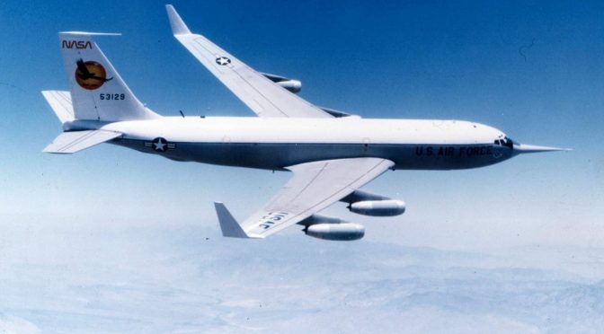
NASA’s Boeing 737-130 was the workhorse of such taxpayer funded testing and developments.  Serial Number SN-19437 (N515NA, tail #515) was born in 1968 (some sources say 1967), and reported for duty at NASA’s Langley Research Center in 1973.  Apparently 515 was the first prototype Boeing 737 built.

I must point out that between 1938 and 1978 the U.S. airline industry was under the total regulation of the federal government, being de-regulated beginning in 1978 with the hopes that capitalist competition would reign in growing costs of operation, but in reality has created the money-grubbing passenger unfriendly monstrosity of today.   Even with de-regulation the airliner industry still relies on taxpayer funded testing of new technologies.

515 took part in dozens of developments:  Microwave Landing Systems, velocity vector display development, CRT electronic cockpit displays, profile descent control law development, total energy control law development,  helmet mounted displays.  Also, satellite-based Global Positioning System for auto-landings, ground-air data-link in lieu of voice communication, traffic flow management ATC-compatible 4-D Flight Management System development, wind shear detection research.  Just to name a few.

In 1985, 515 joined several other NASA and FAA aircraft in the U.S. state of Maine, as well as in Canada, to study Runway Friction in bad weather.

In 1989, 515 got a new paint-job.

According to NASA, 515 was constantly modified, and even had two cockpits, the second cockpit being located where the airliner’s first class passengers would sit.

1990s NASA video showing 515 is use for wind-shear research.  The research was done because of the increasing number of crashes being caused by the weather phenomenon called wind-shear:

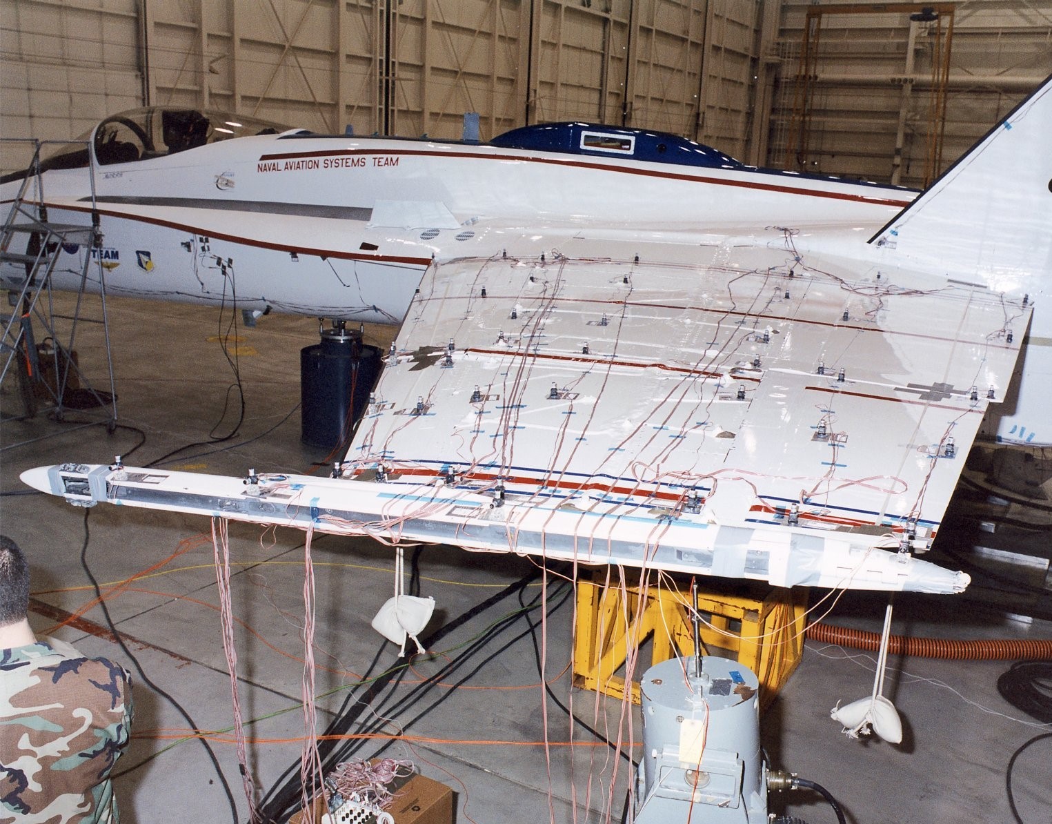
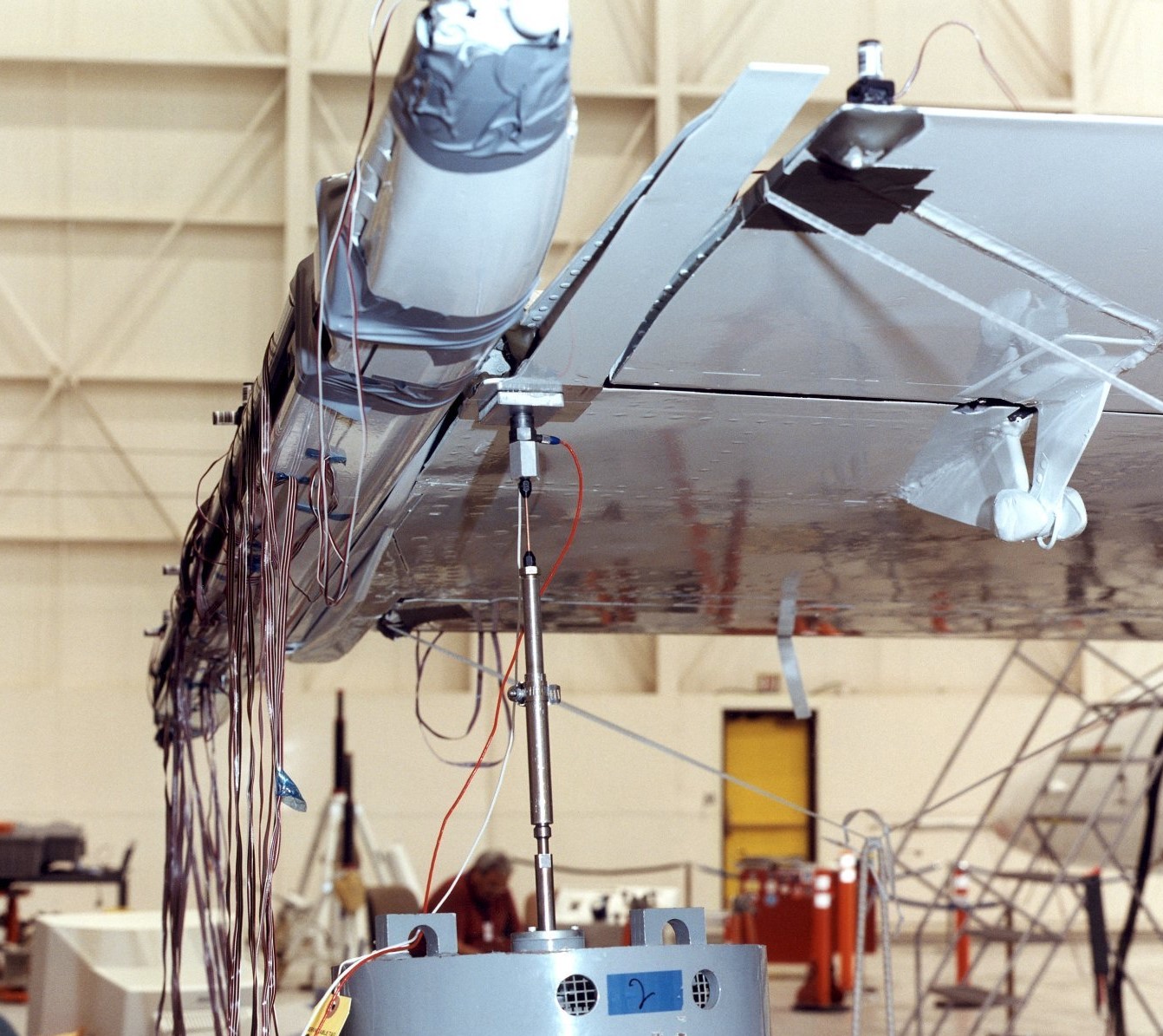
High lift wing testing, 1990s.

515 retired in  2003, and now resides at the Museum of Flight, in Seattle, Washington.

NASA: F-16XL LAMINAR FLOW, ONCE AGAIN NASA SAVING THE AIRLINER INDUSTRY!

NASA’S C-133 APOLLO DROP SHIP


F-16XL Laminar Flow, once again NASA (taxpayers) saving the ‘private sector’ airliner industry!

Photo via NASA, 29SEP1997.

Four different versions of the General Dynamics F-16 shared the ramp at NASA’s Dryden Flight Research Center at Edwards, California, in this 1997 photo. At left and right are the only two F-16XL prototypes built. The two-seat F-16XL-2 version to the left, NASA registration number 848, was flown in a supersonic active/passive laminar flow control experiment until late 1996. The single-seat F-16XL-1 at right, NASA registration number 849 (originally USAF 749), was flown in a variety of experiments, including an earlier passive laminar-flown study and sonic boom attenuation research. At center left is a single-seat F-16A, NASA registration number 816, the only civil registered F-16 in existence. At center right is the U.S. Air Force Advanced Fighter Technology Integration (AFTI) F-16A.

Silent NASA video, F-16XL-1 #849 in-flight 1992:

NASA photo published in 1992.

NASA 849 F-16XL-1 in earlier passive laminar flow experiment.

NASA photo by Judson Brohmer, 1995.

By 1993, F-16XL-1 #849 was returned to original configuration to study the performance of the XL’s ‘cranked arrow’ wing.

NASA photo, October 1991.

NASA 848 F-16XL-2 prior to active/passive laminar flow wing glove modifications.  848 was originally a single seat USAF F-16A #75-0747,  which crashed at the end of 1980, was rebuilt as the first F-16XL in 1981, then rebuilt again as the two seat F-16XL-2 taking its first flight in 1982. 

NASA photo dated February 1995.

Mounting the perforated port ‘active’ laminar flow glove on #848.

NASA photo, June 1995.

This NASA photo shows you how tiny the perforations are in the port glove. The edge of a dime coin is used to show scale, NASA used a laser to drill the 10-million, almost microscopic, holes.

NASA photo dated 1995.

NASA photo dated 1995.

First flight of modified F-16XL-2. NASA photo by Carla Thomas, 1995.

First flight of fully modified F-16XL #848. Notice the wing tip sensors, which were used to study ‘flutter’ on 848 prior to being modified for laminar flow testing. They were not used during the bulk of the laminar flow testing. This NASA video explains the use of the wing tip ‘exciter vanes’ (Excitation System) on 848:

Flying over Lake Mead, Nevada. NASA photo by Jim Ross, October 1996.

A turbo-compressor vacuum mounted in the fuselage, behind the cockpit, draws off a small part of the boundary-layer air flowing over the port wing’s perforated titanium leading edge glove at supersonic speeds, this is known as Supersonic Laminar Flow Control, or active laminar flow system. The turbo compressor exhausts out the starboard side of the fuselage.

NASA photo, 1995.

A turbo-compressor (looking like a axillary power unit, APU) in the aircraft’s fuselage provided suction to draw air through more than 10-million tiny laser-drilled holes in the titanium glove via a manifold system employing 20 valves.

NASA photo published in 1996.

In some photos you’ll notice a small canard, known as a ‘shock fence’, protruding from under the leading edge.  In a few photos it’s not present.

NASA photo by Jim Ross, April 1996.

Note that the leading edge on the starboard side is different.

Refueling on its 45th and final data-collection flight, November 1996.

The starboard leading edge was known as the passive laminar flow system.

45th and final data-collection flight of F-16XL 848, November 1996. NASA photo by Jim Ross.

NASA video, one hour of ‘raw’ (unedited) video of F-16XL-2 in flight:

Data obtained during the program was collected in the hopes of developing civilian transport aircraft (specifically Boeing, Rockwell, and McDonnell Douglas) that could cruise at supersonic speeds.

WINGLETS, OR ONCE AGAIN NASA SAVES THE PRIVATE SECTOR!

NASA’S TUPOLEV 144 SST

NASA’s C-133 Apollo drop ship

A 13-thousand-pound (5896.7-kilos) Apollo Command Module 19A test mock-up (aka boilerplate) was used to test various systems before the actual Apollo was launched, including parachutes.

NASA photos.

On 03JUL1968, NASA’s C-133 Cargomaster drops the Apollo ‘boilerplate’ for parachute (aka Earth Landing System) testing.

The first ELS test was conducted on 03MAY1963.  Between 1963 and 1968, 34 drop tests, using various ‘boilerplate’ modules with different parachute configurations, were completed.

Silent NASA video:

‘Boilerplate’ coming down on the Southern California-El Centro desert, 16JUN1968.

Original Northrop Ventura Corporation documentary film:

See an actual boilerplate module at Columbia Memorial Science Center, in California.

NASA photo 1963.

NASA also used the C-133 to haul what was called the Centaur Upper Stage shuttle rocket.  The Centaur Upper Stage shuttle rocket has been periodically brought back to life as a cheaper alternative to the Space Shuttle.  NASA C-133s also transported stages for Atlas, Saturn and Titan rockets to Cape Canaveral, Florida.

NASA’s Viking, no not the Mars Landers! 

Travis Air Force Base: C-133 Cargomaster

NASA Viking, no not the Mars landers! Or, last flight of a Viking.

In July 2021, NASA retired the last operational S-3B Viking.  It’s home is now the San Diego Air & Space Museum-El Cajon Gillespie Field Annex.  This ended 20 years of NASA service for an aircraft that had already completed a career with the U.S. Navy.

NASA photo dated 2001.

In January 2009, the U.S. Navy officially retired (from ‘fleet service’ aboard aircraft carriers, with final USN retirement in 2016) its Lockheed S-3B Viking aircraft.  In 2001, one lucky Viking got a new life with the National Aeronautics Space Administration.

Glenn Research Center, Ohio, NASA photo dated 2001.

Even before the USN began retiring their Vikings NASA was already prepping to use it, in 2006 awarding Boeing a contract to rebuild the Viking. 

NASA photo dated 2006, Glenn Research Center, Ohio.

NASA Airborne Science Program’s N601NA Viking before getting its new NASA clothing, still wearing its worn-out U.S. Navy uniform.

NASA photo dated 2007, Glenn Research Center, Ohio.

This NASA image, of Viking N601NA with its new NASA uniform, is from 2007.

NASA photo dated 2007, Glenn Research Center, Ohio.

NASA began using the Viking, to supplement their other aircraft, to fly aircraft SatCom (satellite communication) relay viability missions over Illinois.

NASA photo dated 2007, Glenn Research Center, Ohio.

NASA photo dated 2007, Glenn Research Center, Ohio.

Photo by Louis DePaemelaere.

N601NA stopping in Grand Junction, Colorado, for fuel.  N601NA was taking part in icing research.

NASA photo dated 2008.

A 1/3 scale model section of S-3B Viking wing inside NASA’s icing tunnel.

In 2010, NASA’s Viking began airborne environmental science missions (like the growing problem of algae blooms in The Great Lakes) and aeronautics research.

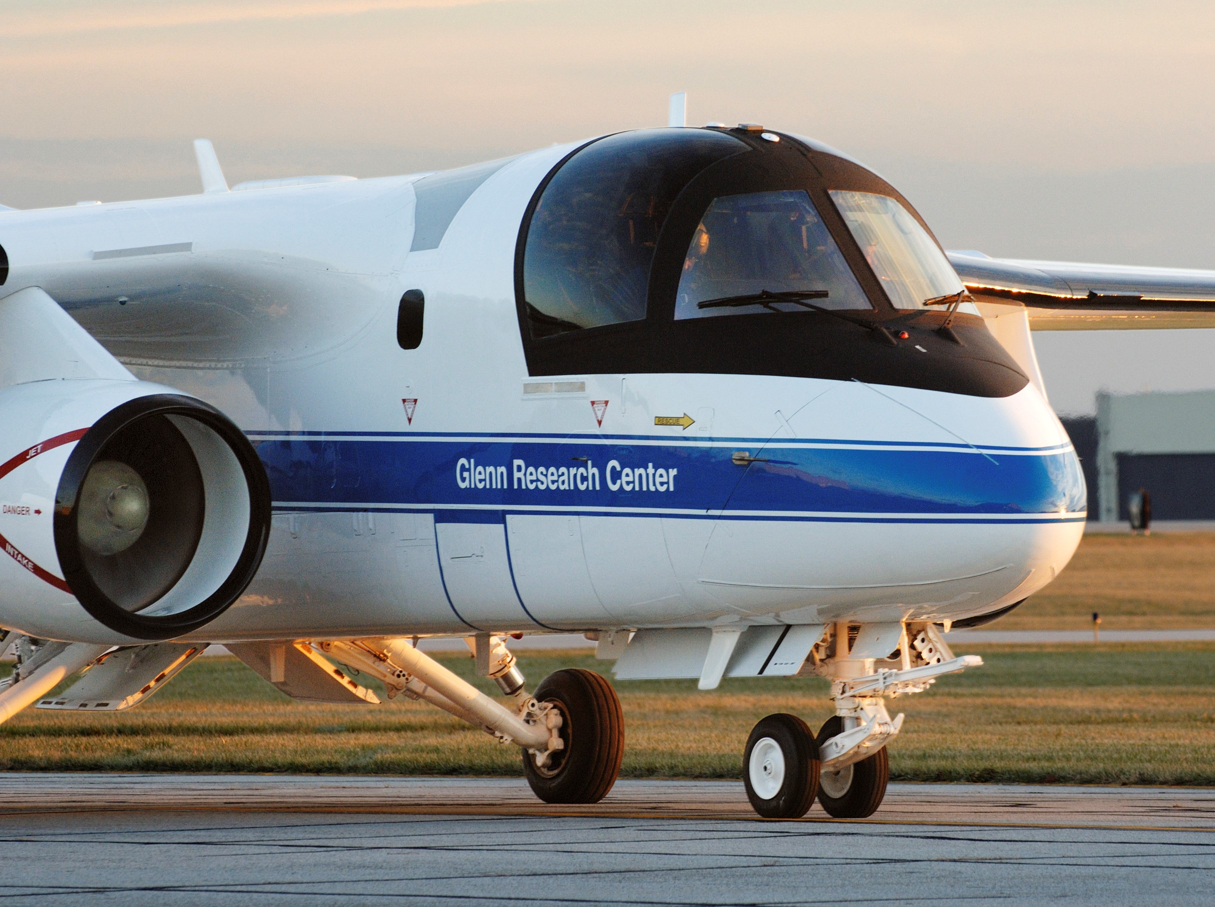
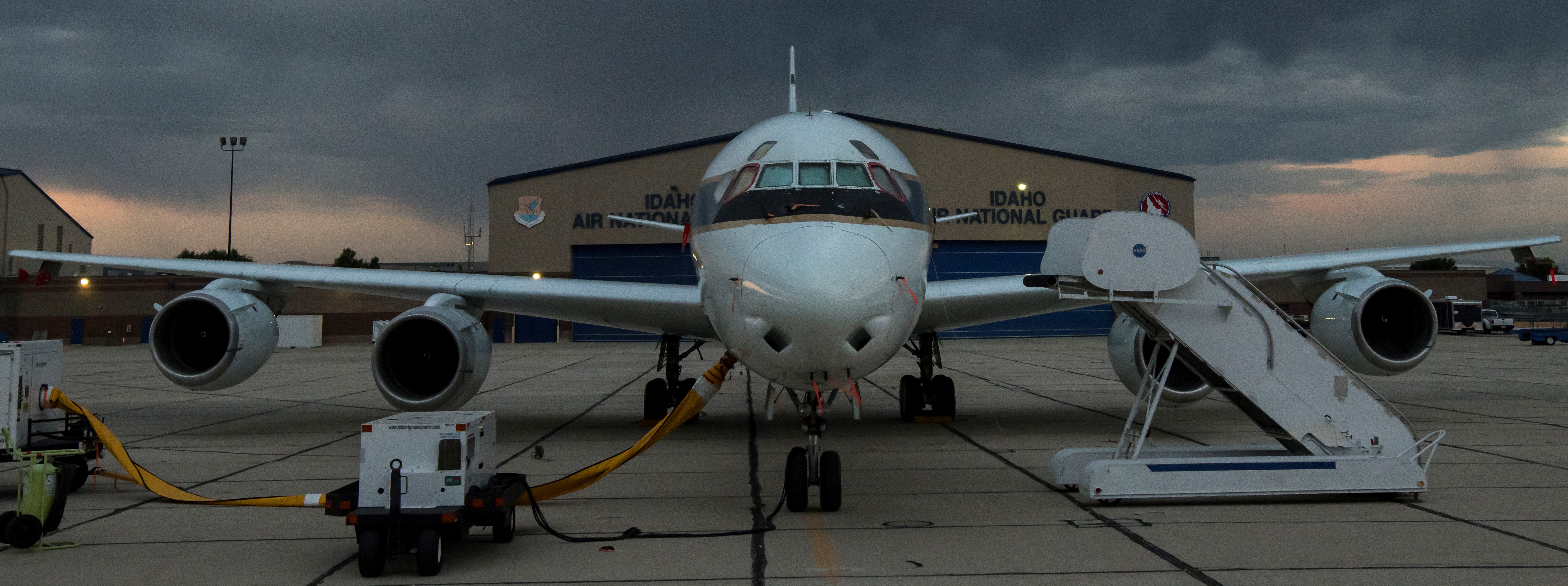
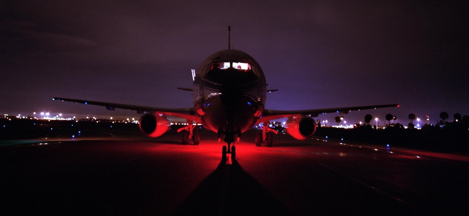
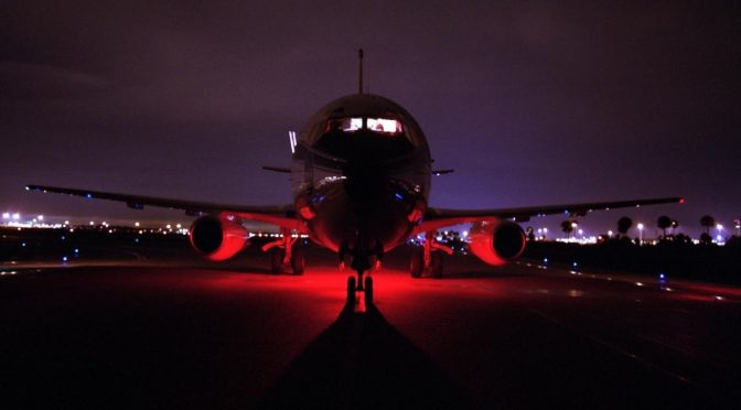
Final approach to the runway at Air Force Plant 42, NASA Dryden’s Aircraft Operations Facility in Palmdale, California, October 2010.  The large cargo pod has been modified by NASA to carry electronic sensing devices for various missions.

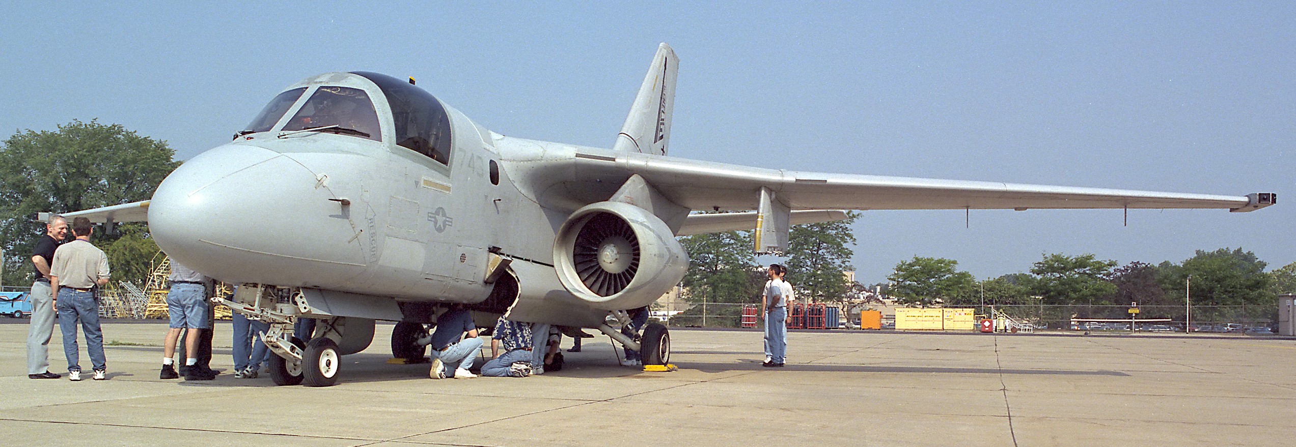
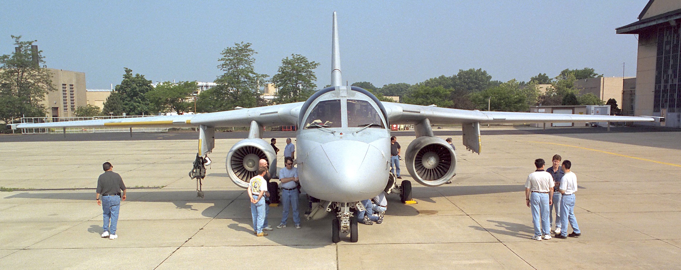
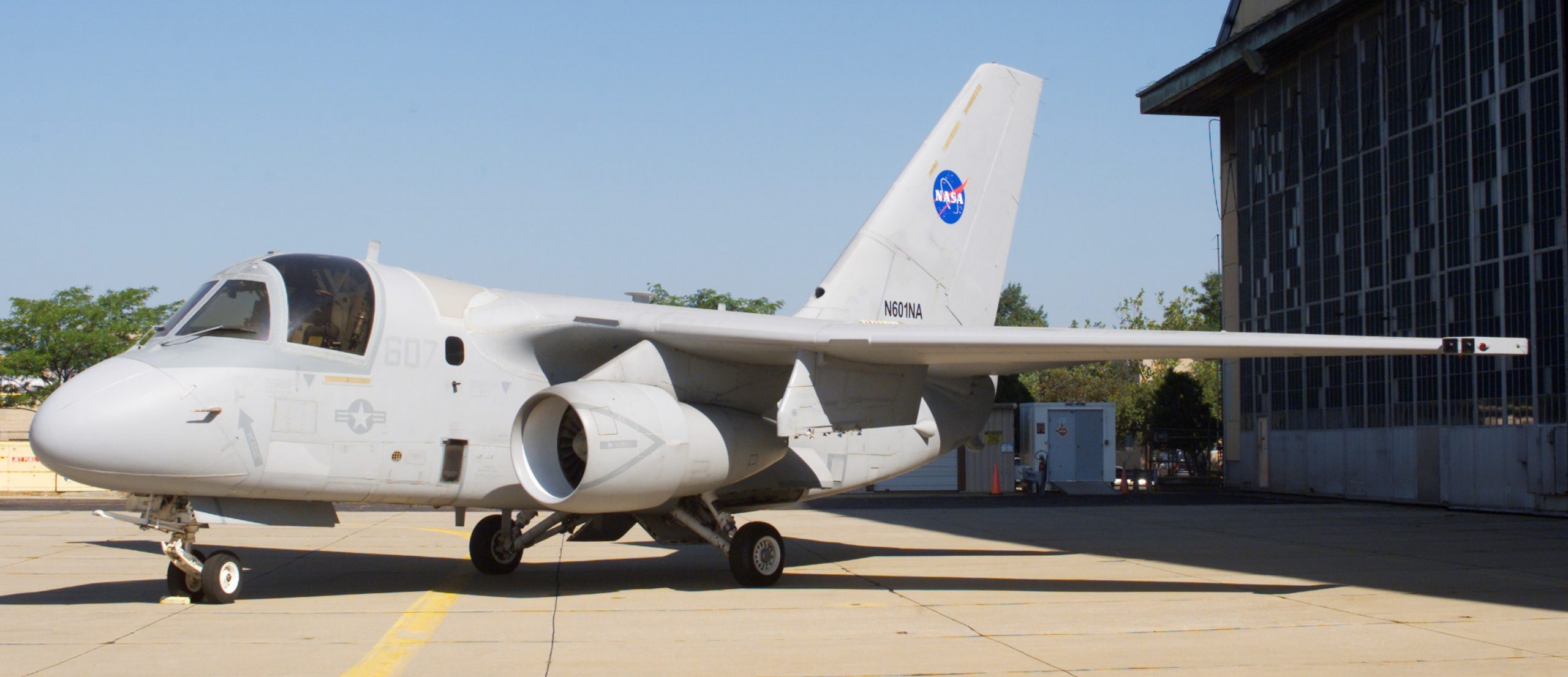
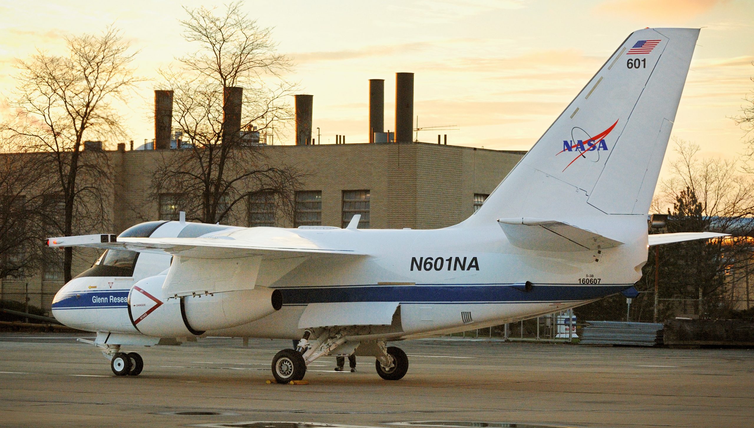
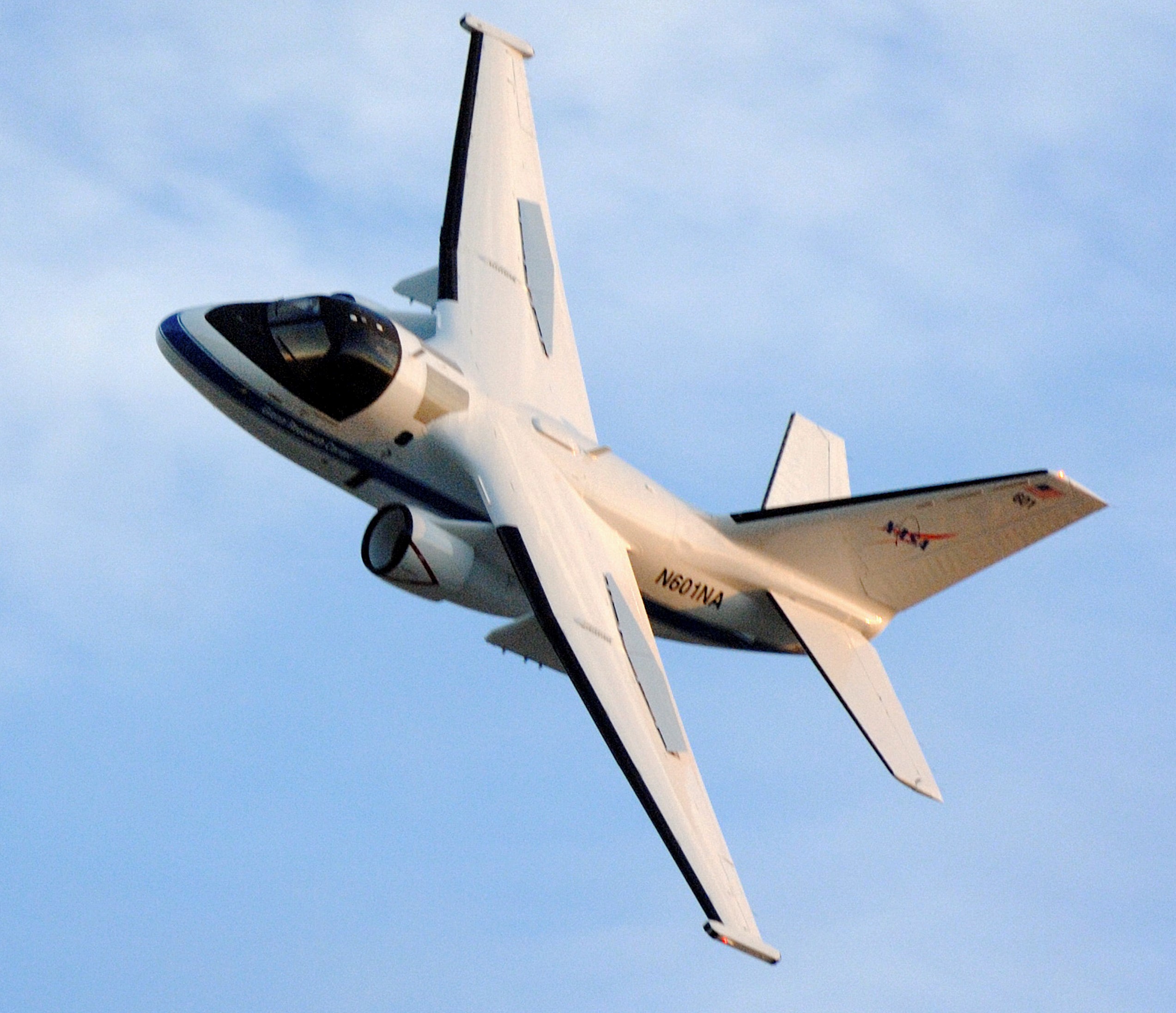
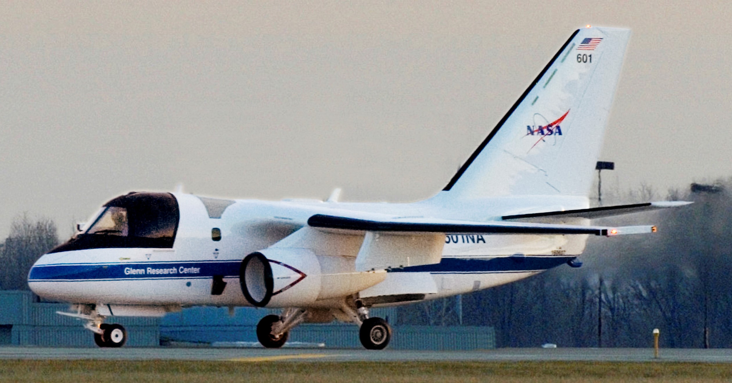
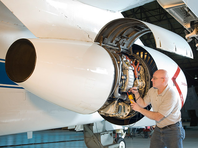
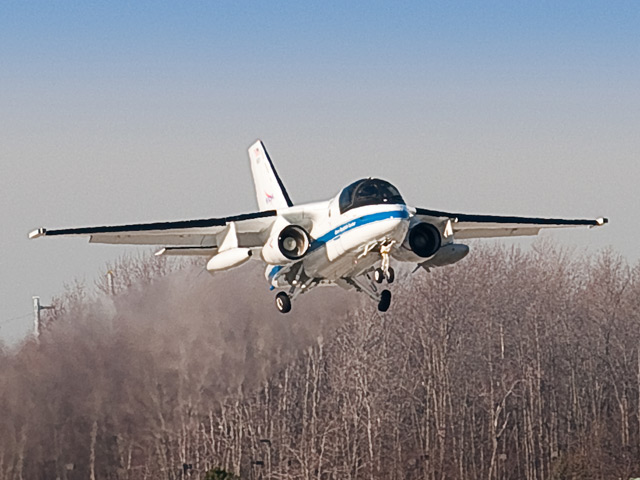
S-3B Viking taking off from Cleveland Hopkins Airport, Illinois.

In the hanger at Glenn Research Center.

In 2014, USN’s VX-30 hosted N601NA, as the NASA crew visited the Bloodhounds for simulator training.

U.S. Navy photo, 18DEC2015.

The last flight of two U.S. Navy Air Test & Evaluation Squadron 30 (VX-30 Bloodhounds) S-3B Vikings over Point Mugu, California, 18DEC2015. 

U.S. Navy photo, 18DEC2015.

  According to the information that came with these U.S. Navy photos, in January 2016 one of these Air Test & Evaluation Squadron 30’s Vikings was sent to be mummified in ‘the boneyard’, while the other got a new life working for NASA.  However, I can’t find anything from NASA confirming they took possession of another Viking.  I’ve even seen some blogs that claim NASA has three Vikings which, again, I haven’t found anything from NASA backing that up.  Current NASA information indicates there was only one Viking in their possession, N601NA, operating out of Glenn Research Center in Ohio.


WINGLETS, OR ONCE AGAIN NASA SAVES THE PRIVATE SECTOR!

Vehicle I-D: NASA DC-8 climate warrior

Bare Metal: NASA trucks save the trucking industry

NASA’S Russian TUPOLEV 144 SST

Vehicle I-D: NASA CANBERRAS, B-57B ‘HUSH KIT’ & WB-57F RIVET CHIP/SLICE

Winglets, or Once again NASA saves the Private Sector!

In another fine example that the capitalist country of United States spends taxpayer money to help-out private sector corporations; between 1979 and 1980, NASA used a KC-135 to special-test the use of winglets in reducing drag and thus reducing fuel consumption.  The study led to the use of winglets on commercial aircraft.

The winglets were developed by NASA’s Richard Whitcomb, who discovered through wind-tunnel testing that winglets could actually produce forward thrust.  Whitcomb is also credited with developing the supercritical wing, also used by commercial airliners (F-8 SUPER-CRITICAL-CRUSADER, FATHER OF MODERN AIRLINER WING DESIGN).

Silent NASA video:

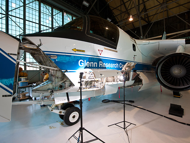
The winglets used by NASA were much bigger than the winglets being used by the commercial sector.

The U.S. Air Force’s -135 family of aircraft are not modified Boeing 707s!!!   It’s amazing to me that even aviation periodicals will refer to the -135 as having evolved from the 707.  Both the -135 and the 707 evolved from the earlier prototype 367-80 (first flight 1954), the -135 (first flight 1956) was actually created before the 707 (first flight 1957).  The -135, also known as the Boeing 717, is smaller than the 707 and structurally there is nothing similar about the two aircraft (like the fuselages having totally different cross sections, the 707 being taller and wider), the major components cannot be interchanged.

Some confusion can be blamed on Boeing itself, as the manufacturer offered militarized 707s to other countries’ air forces, such as Iran (which got both 707s and 747s converted for use as airborne fuelers).  Boeing’s militarized 707 production continued into the 1990s, they are nothing like the -135.


KC-135:   BATS & BEARS, OH MY!

Bare Metal: NASA TRUCKS saving the trucking industry

Vehicle I-D: NASA’s DC-8 climate warrior

The former Douglas airliner is a -72 model, and can stay airborne for 12 hours and has an operational speed between 3-hundred and 5-hundred knots (345-575mph, 555-926kph).

The research flights are made as low as 5-hundred feet (152 meters) and as high as 42-thousand feet (12-thousand-801 meters or 12.80 kilometers).

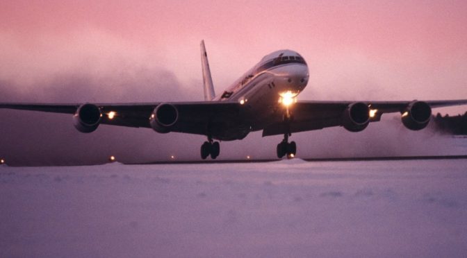
DC-8-72 on the ground in Chile after an 11 hours flight to study ocean ice, October 2009.

The information that came with this pic stated the DC-8 was being used to test alternative fuels in California, January 2009.

The DC-8-72 uses a plethora of electronic equipment for remote sensing scientific studies in archeology, ecology, geography, hydrology, meteorology, oceanography, volcanology, atmospheric chemistry, soil science and biology.  The name of the organization/university conducting the study is sometimes painted on the forward section of the fuselage, underneath the Dryden Flight Research Center name.

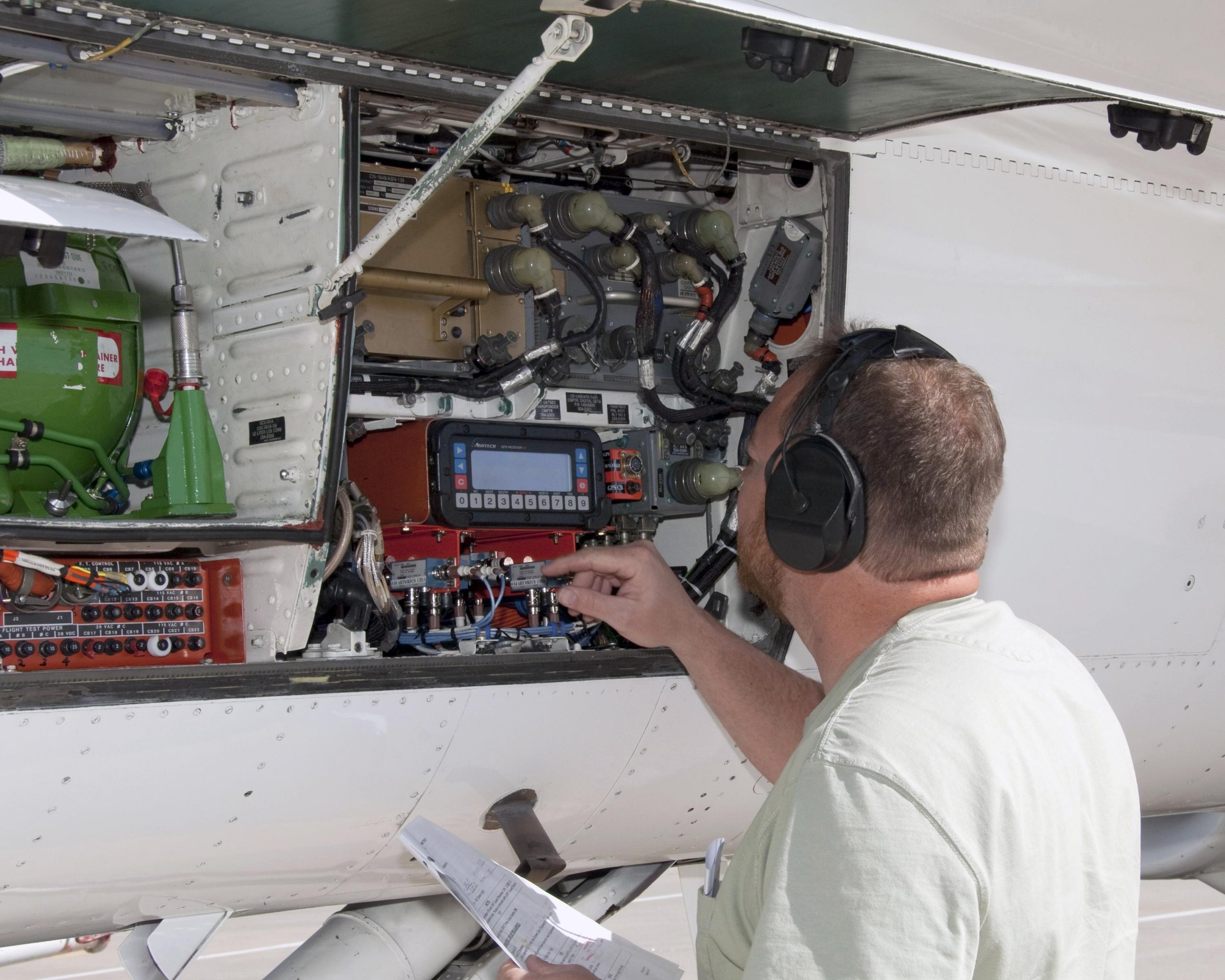
Preparations for Operation Ice Bridge, Dryden Aircraft Operations Facility, California, late 2009.  The cart full of computers is part of a Laser Vegetation Imaging Sensor, waiting to be installed on the DC-8.

Inside the DC-8 Airborne Laboratory, being configured for Operation Ice Bridge, 2009.

DC-8 on approach to Dryden Aircraft Operations Facility, November 2008.

From November 1999 to March 2000, the DC-8-72 joined a NASA U-2 (aka ER-2) for SAGE III Ozone Loss and Validation Experiment (SOLVE), in Sweden.

In 2019, IDAHO, KANSAS, UTAH were HOME BASES FOR NASA’S DC-8 FIREX-AQ! (also has videos of climate sniffing ops over Germany and Korea)

For more info visit NASA’s official DC-8 website

NASA ‘CLIMATE SPY PLANE’ PROVES CALIFORNIA’S STRICT ANTI-POLLUTION LAWS ARE A JOKE!

B-25 Flamin’ Maimie was as cold as ice!

Before there was NASA, there was NACA (National Advisory Committee for Aeronautics).  Photos from the NASA archives.

Looks to be Flamin’ Maimie before NACA’s many modifications. NACA photo, 1947.

NACA had a XB-25E called Flamin’ Maimie.  If you look up Flamin’ Maimie you’ll get a couple of dominant results; a jazz song from the 1920s by the band The Coon-Sanders Nighthawks, and a big-hair female track team from Abilene, Texas, who became the first female sports team to make the cover of Sports Illustrated, in 1964.

NASA photo, 1947.

While the jazz-dance song and the track team were about ‘hot’ women, NACA’s Flamin’ Maimie was about being as cold as ice.

NASA photo, 1947.

Originally the XB-25E was used by the U.S. Army Air Force (USAAF) from 1942-44.  It was a modified B-25C.  The hot exhaust gasses were routed through the flying surfaces of the bomber.  It was successful, but apparently the USAAF decided the added weight of the hot air de-icing system wasn’t justified.  In July 1944, NACA became the new owner of Flamin’ Maimie.

NASA photo, 1949.

NACA added these protruding therm-o-meters.

NASA photo, 1950.

NACA used Flamin’ Maimie to study new de-icing technologies, and the processes which caused aircraft to collect ice.  The program operated out of Ohio, from the Lewis Flight Propulsion Laboratory (now known as NASA Glenn Research Center), until 1953.

NASA photo, 1950.

The NACA pressure icing rate meter data recorder used in the XB-25E.

NACA’s diagram of de-icers on B-25, dated 1946.

I was not able to find any information as to what happened to XB-25E Flamin’ Maimie, other than NACA “transferred” it in February 1953.

B-25 ¡PANCHITO!