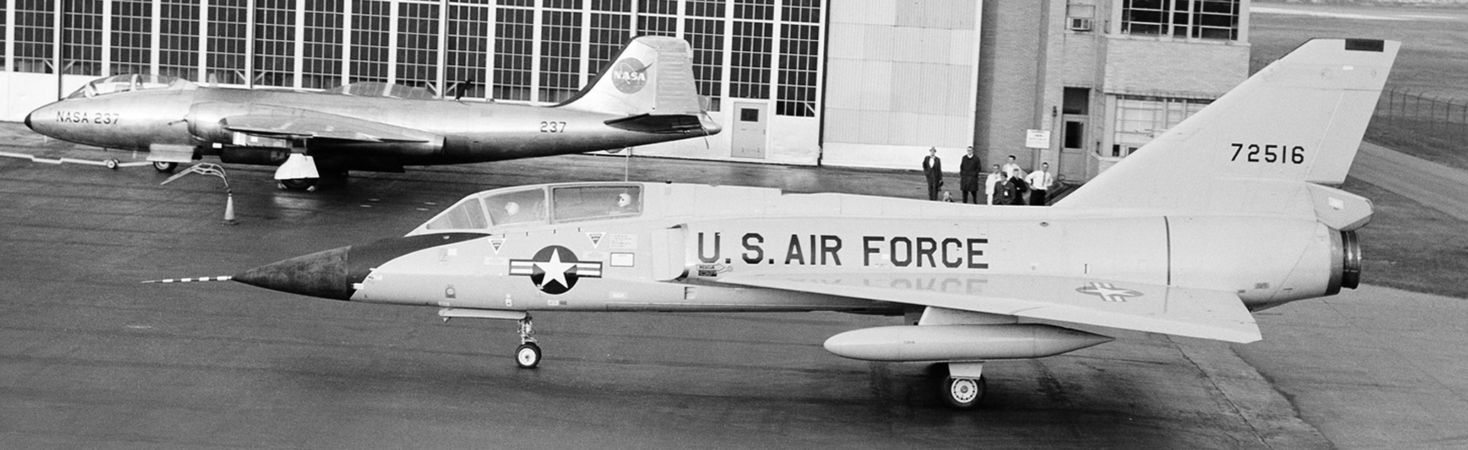
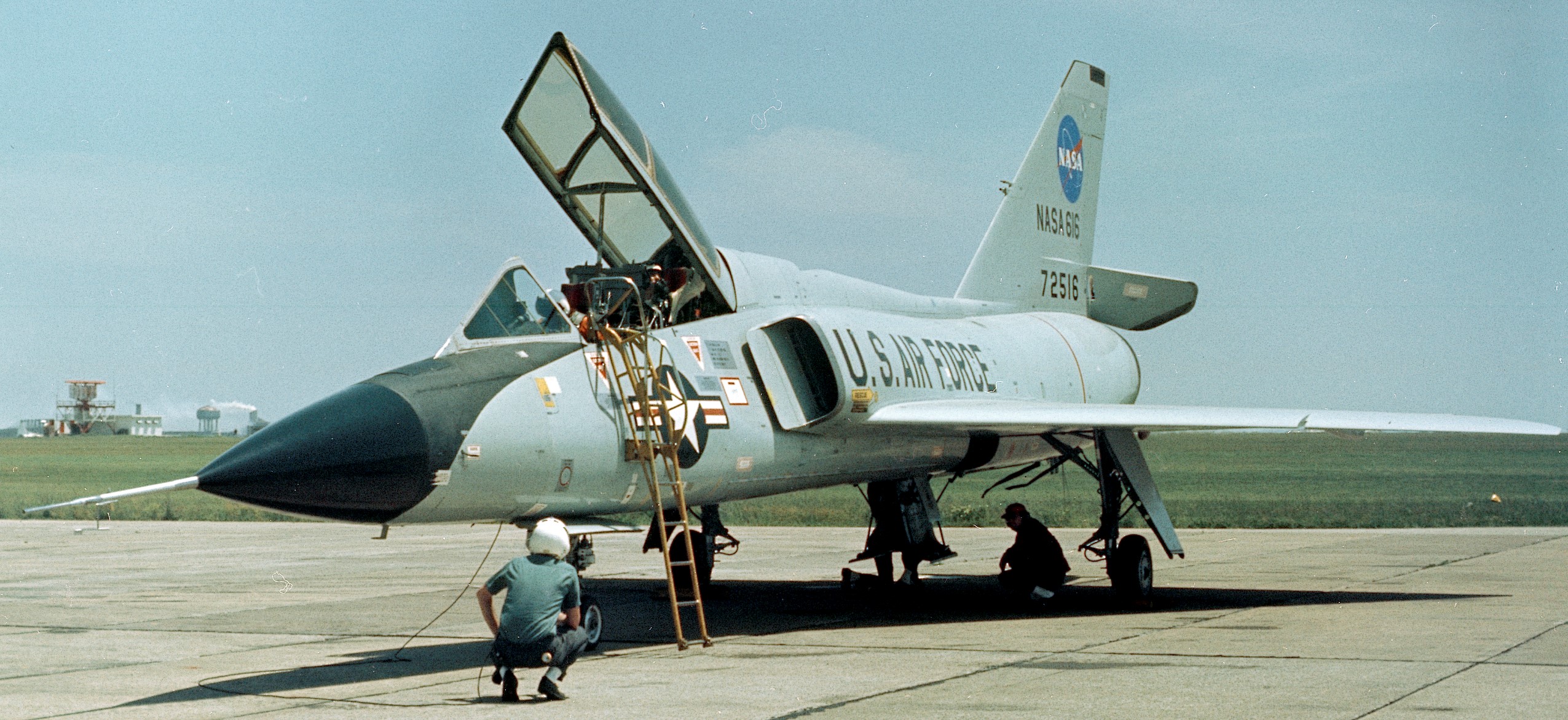
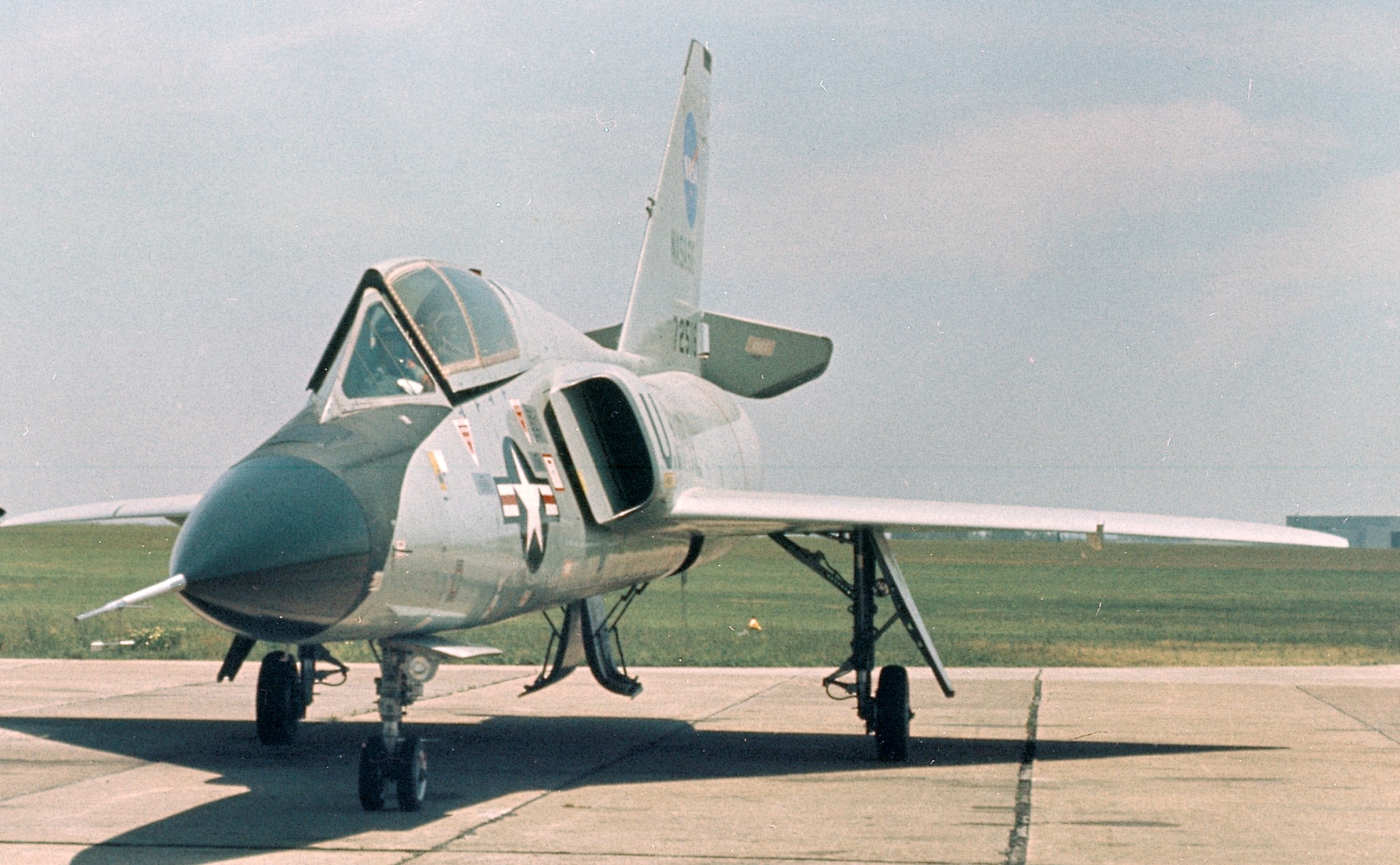
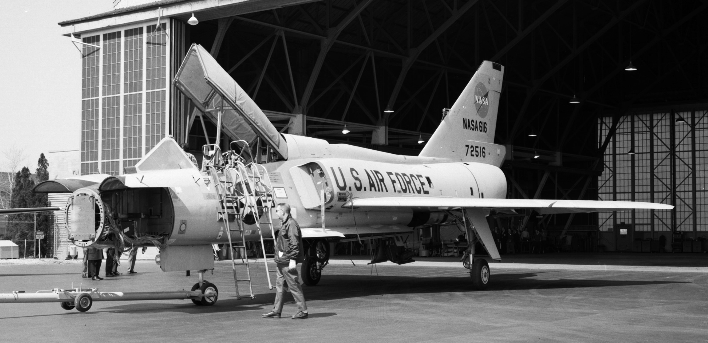
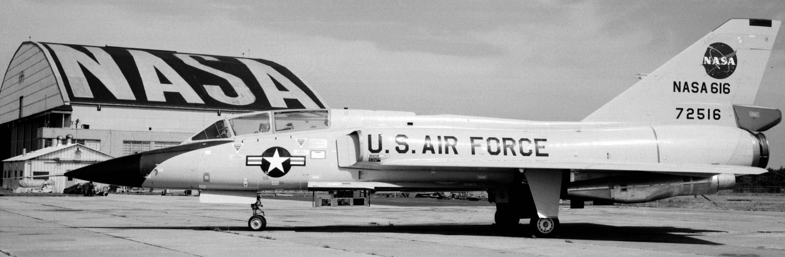
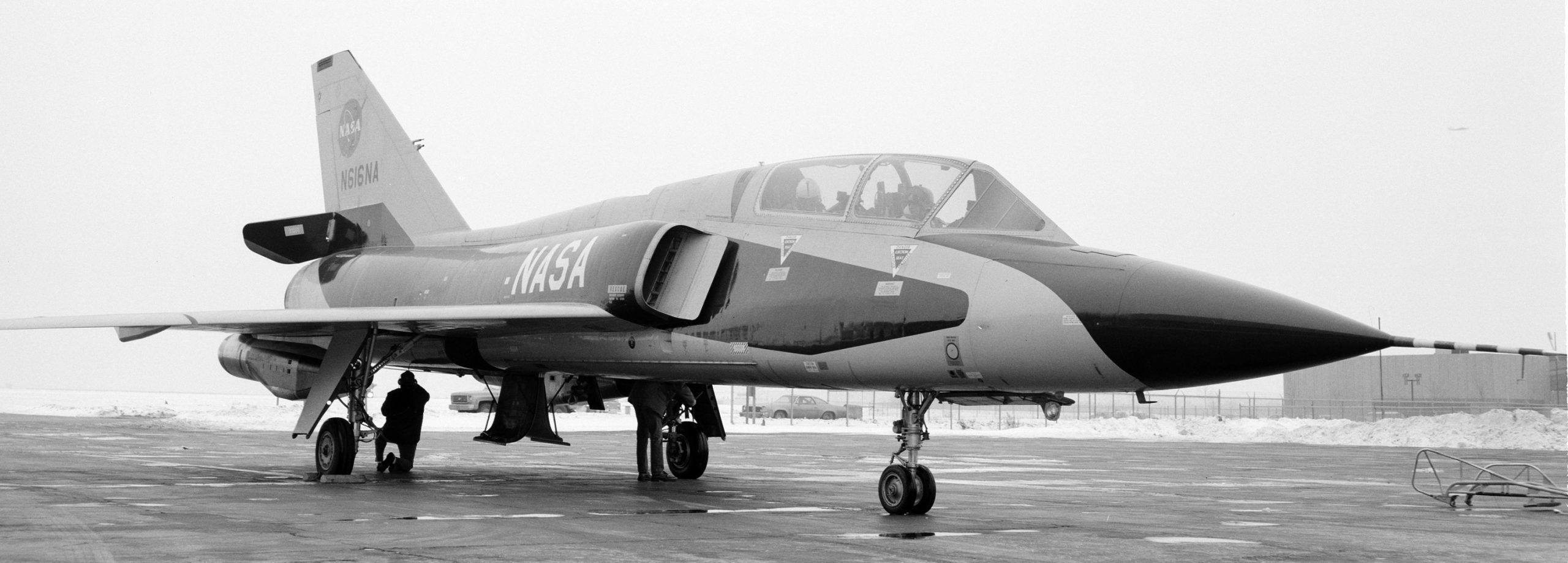
Soon to become ‘616’, day of delivery to NASA from USAF, 31OCT1966. NASA photo.
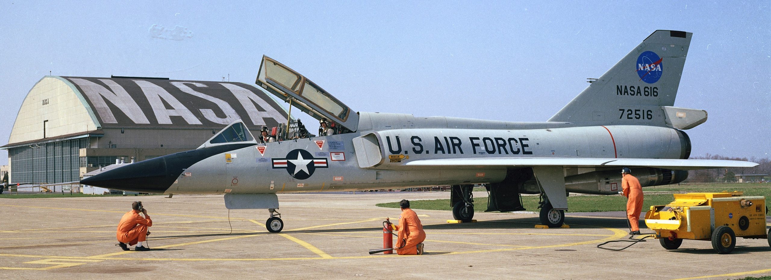
In 1966, NASA took possession of a USAF F-106B that had been used to test ejection seats and radar systems.
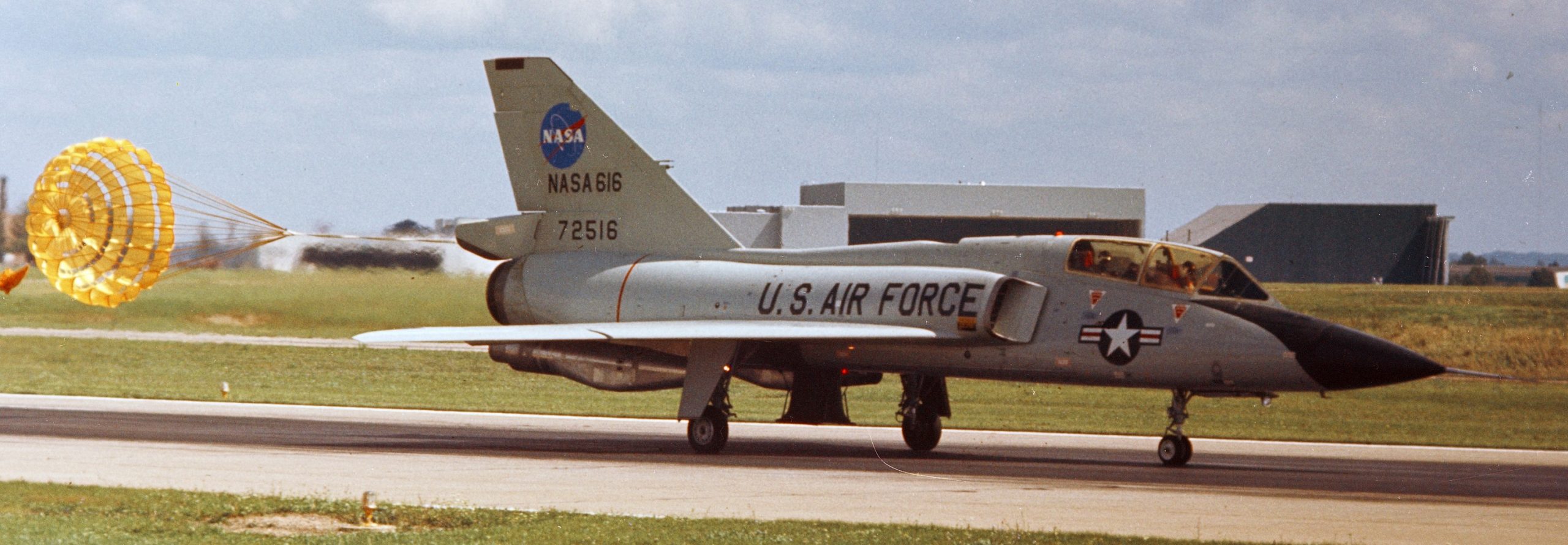
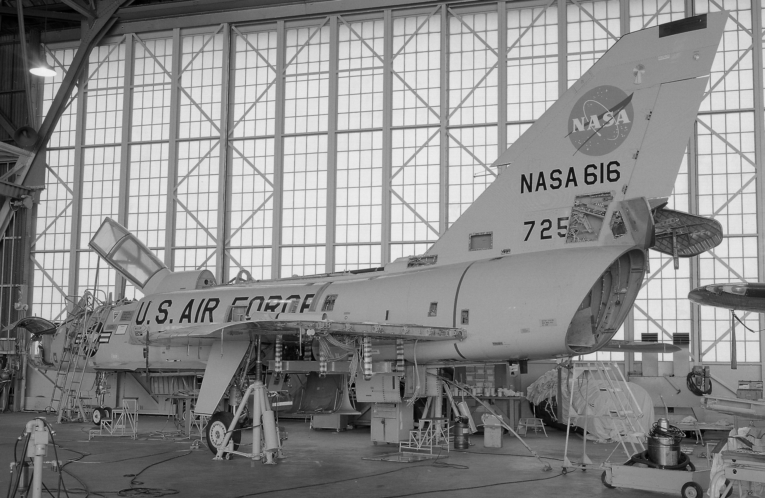
NASA photo, 1969.
NASA photo.
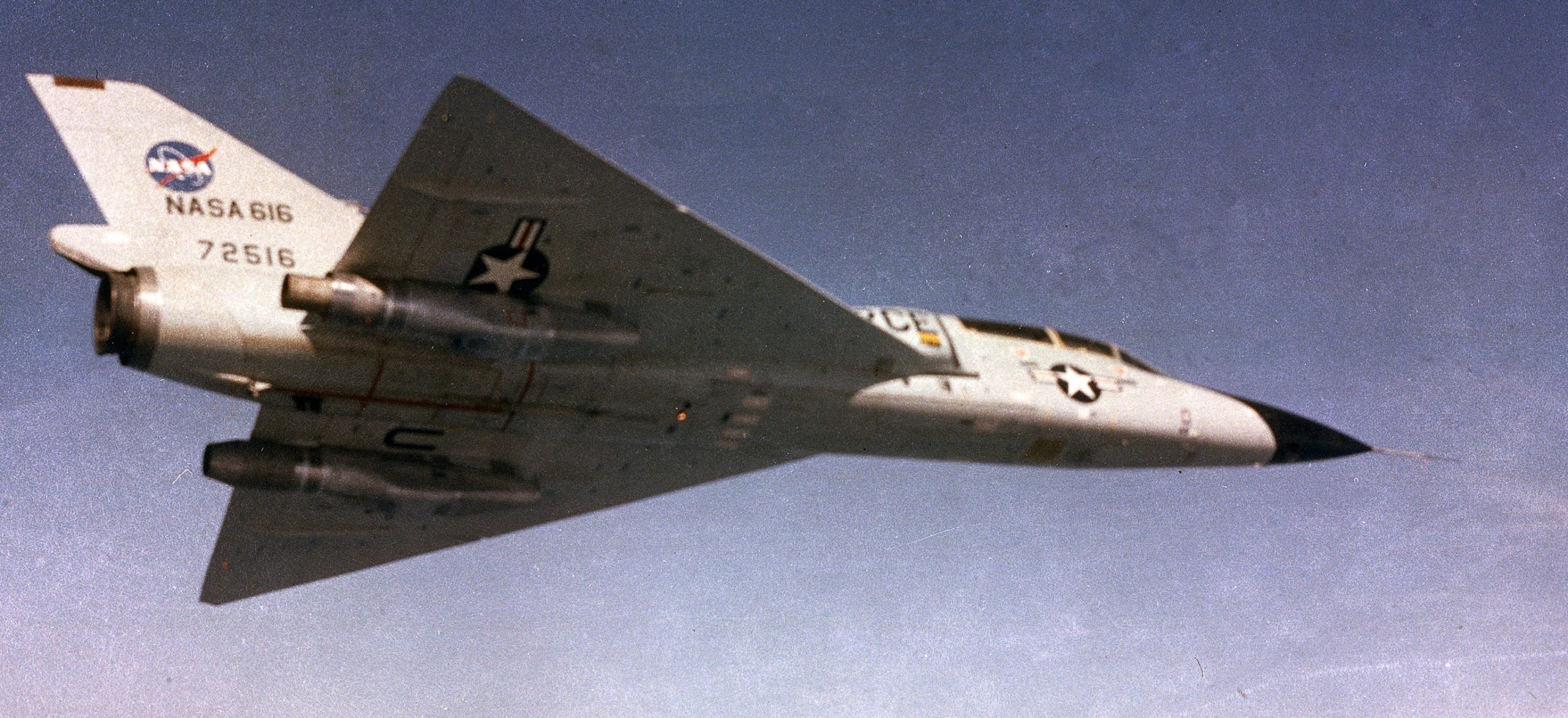
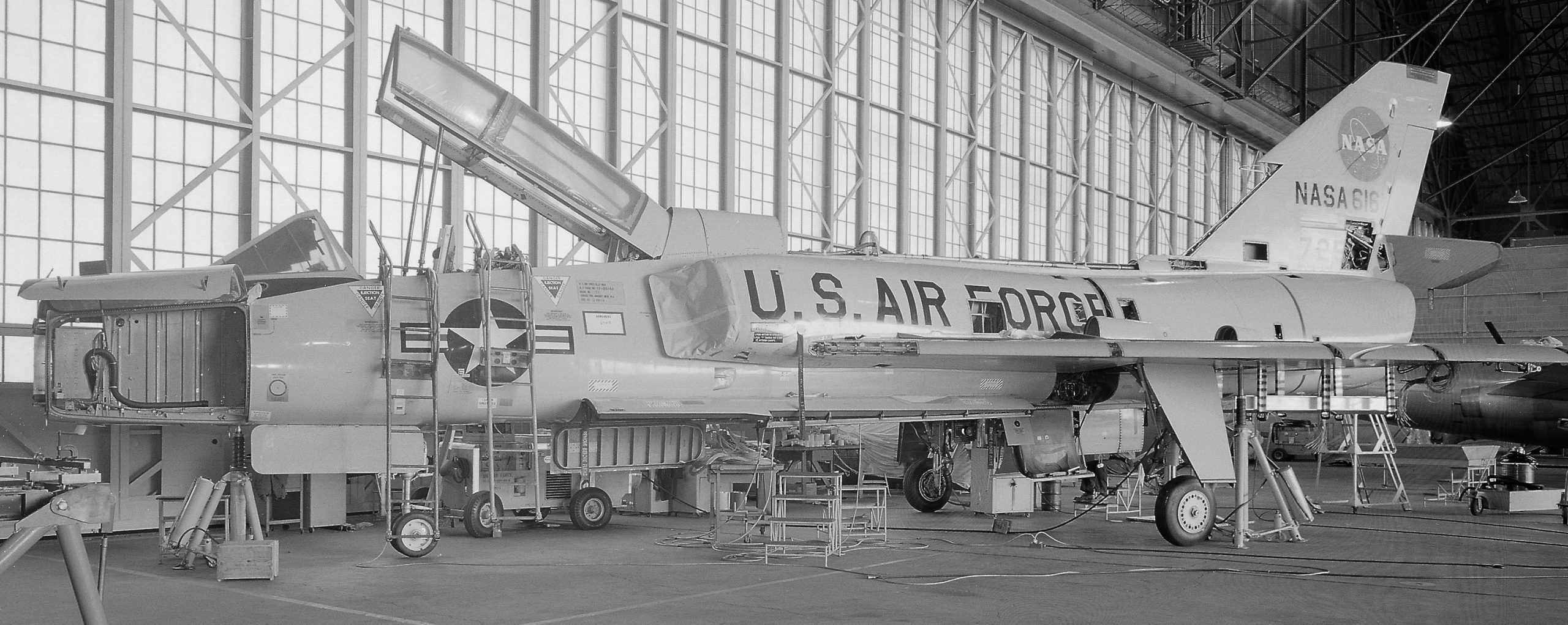
Something different about this F-106B.
NASA photo, 1969.
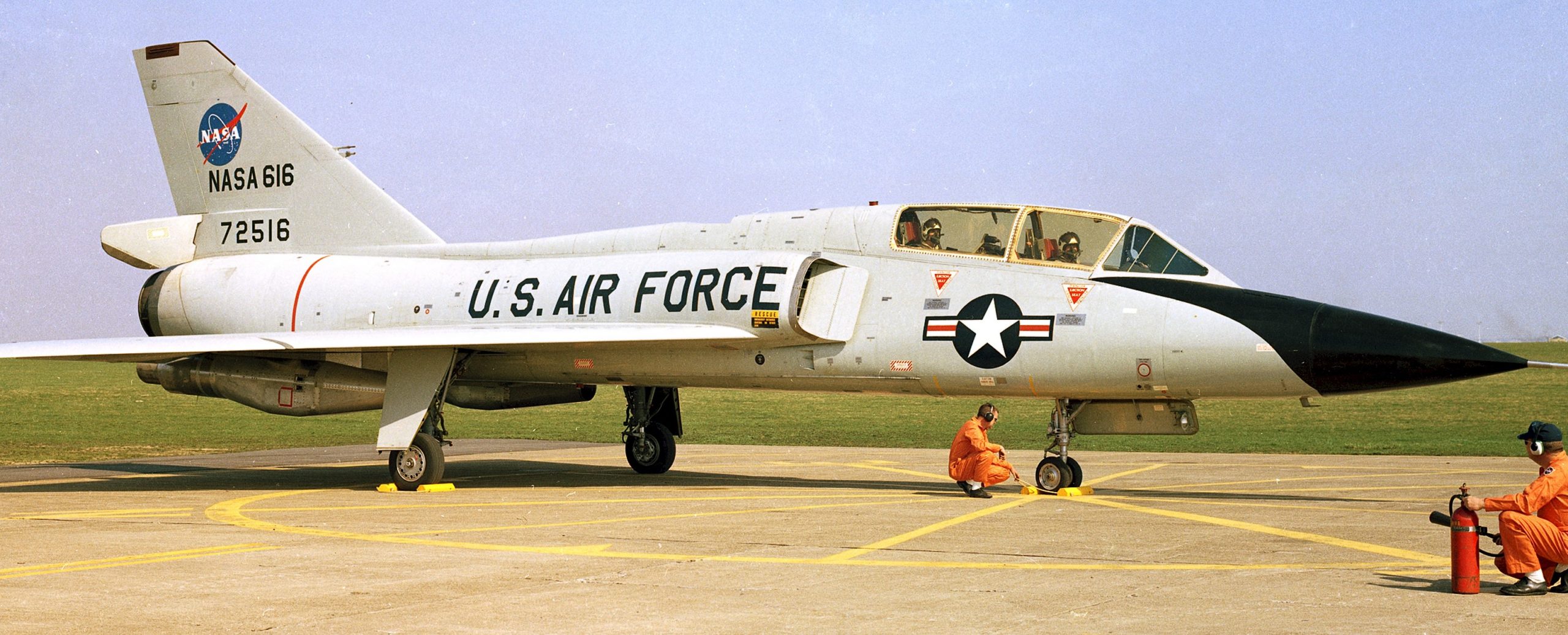
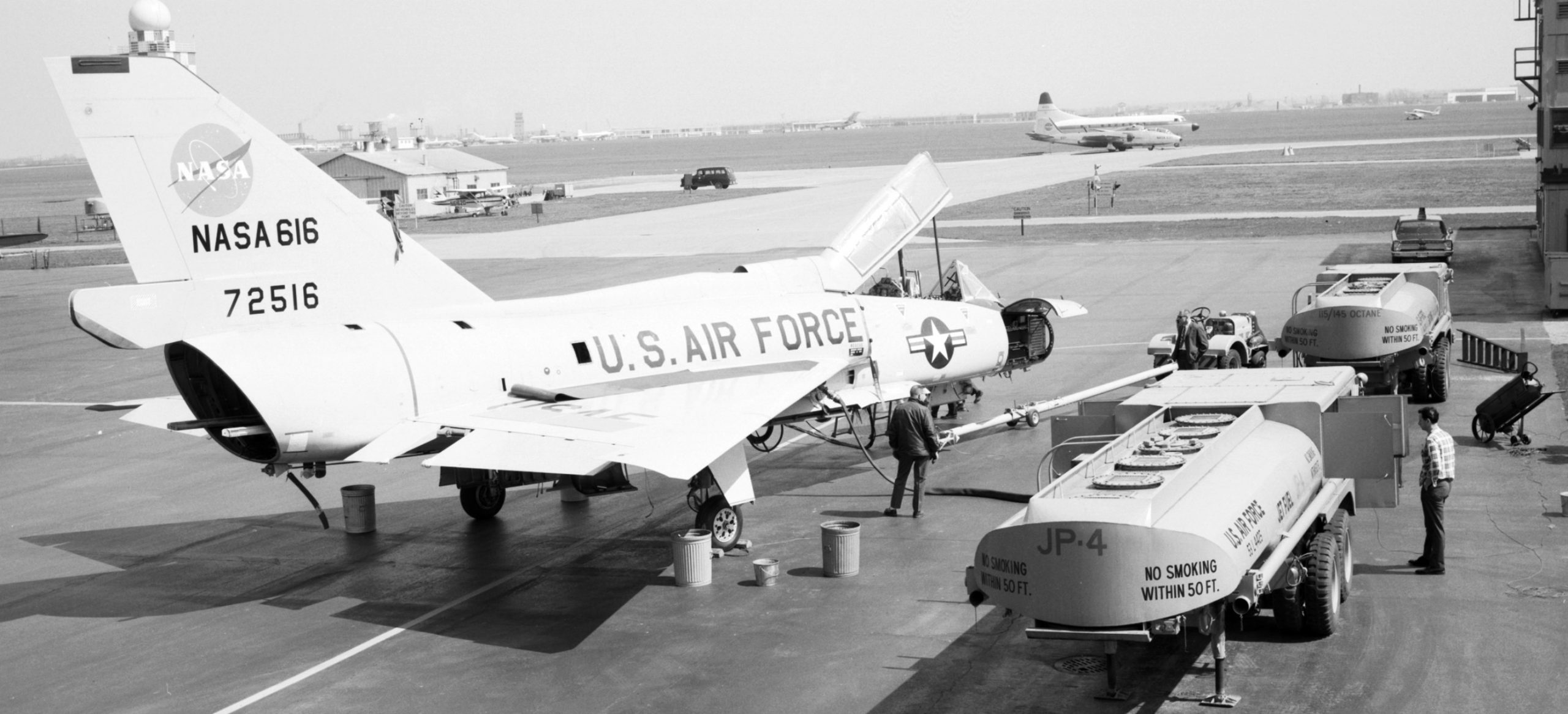
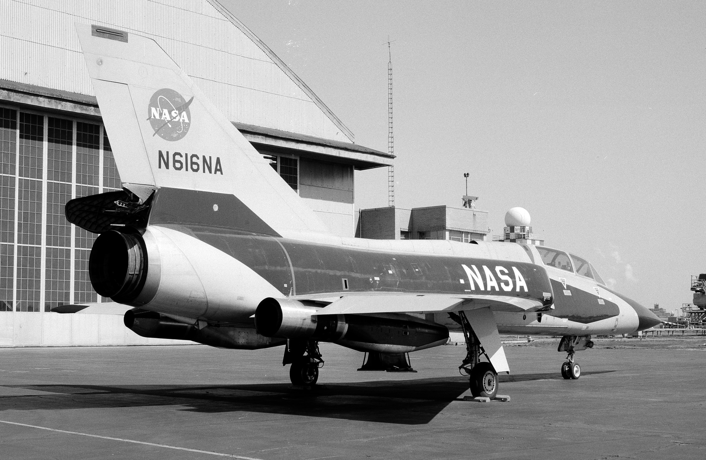
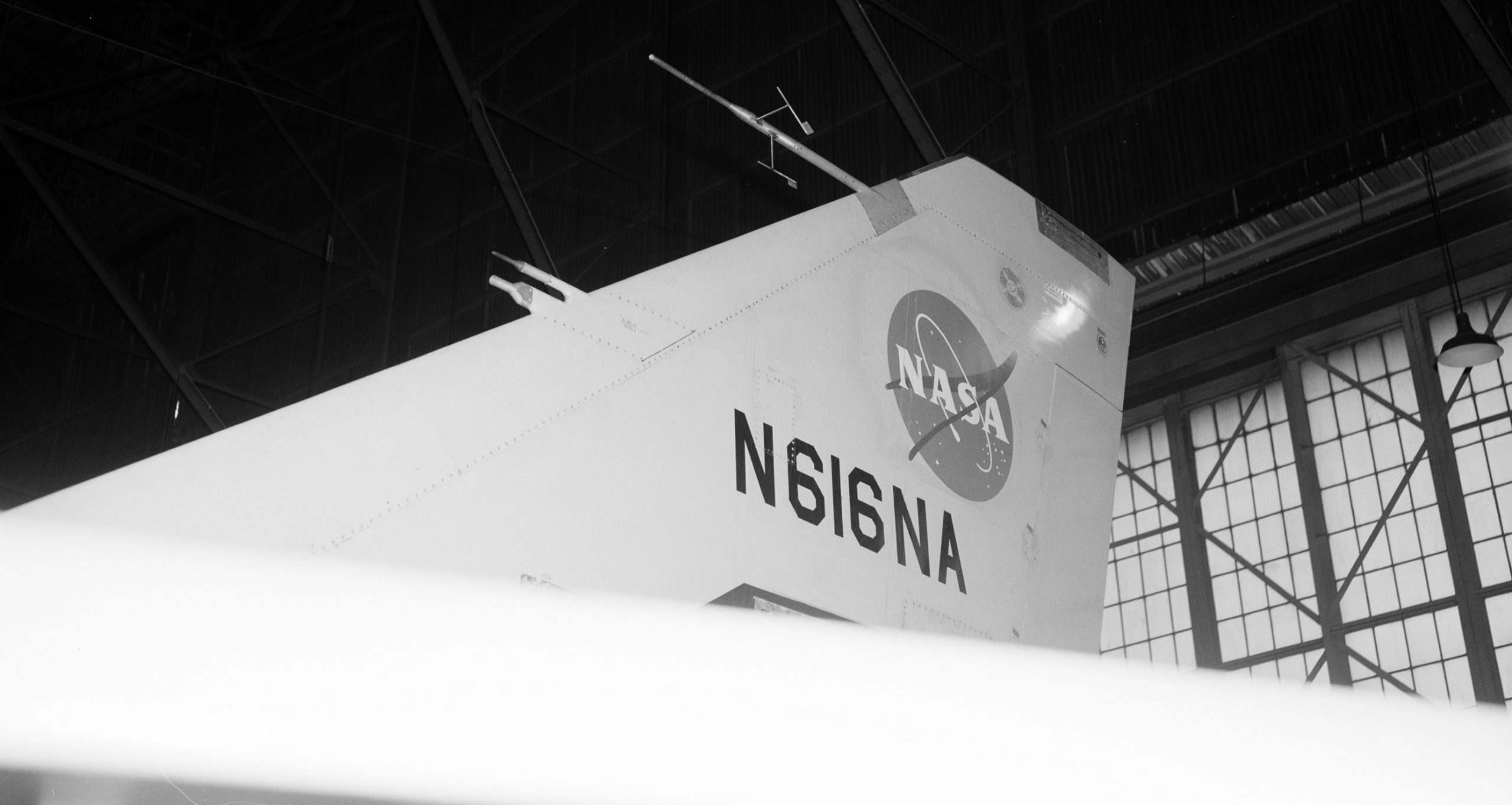
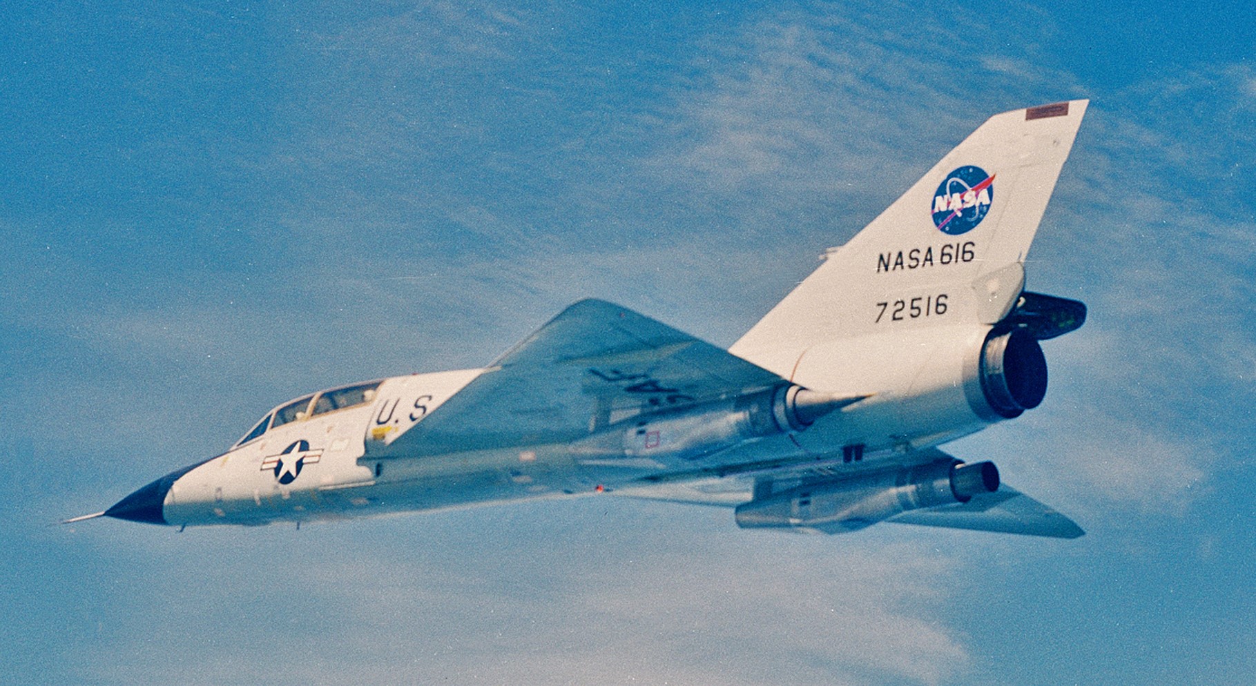
NASA tail code 616 while in use at Lewis Research Center, Ohio, and changed to 816 while at Langley Research Center, Virginia. USAF tail code 72516.
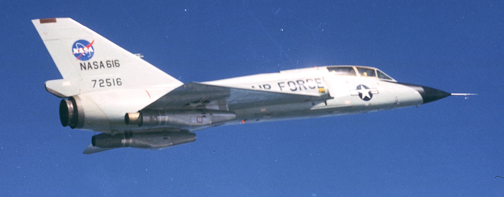
NASA photo, 1969.
NASA photo, 1969.
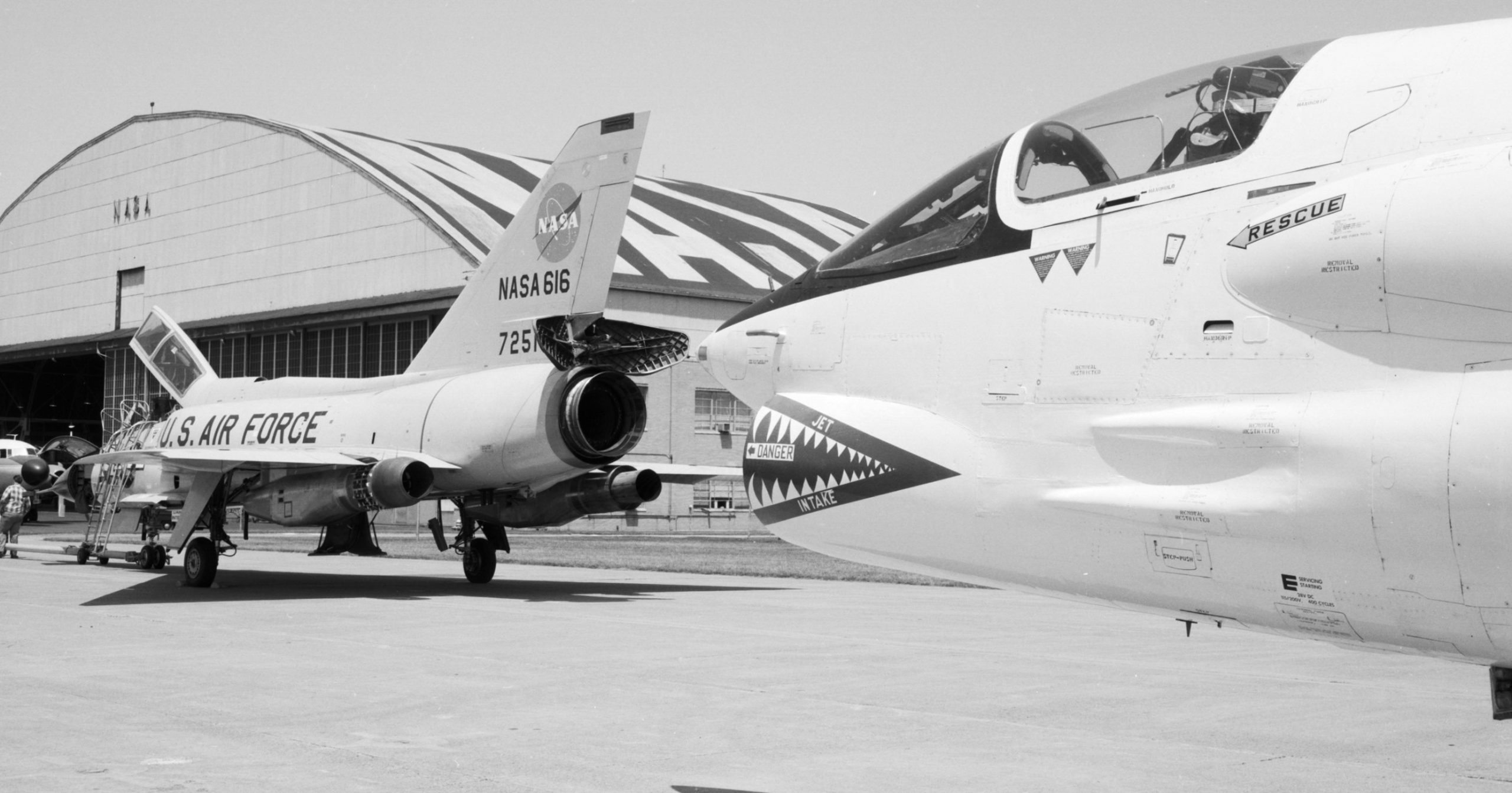
F-106B and its F-8 Crusader ‘chase’ plane. NASA photo, 1969.
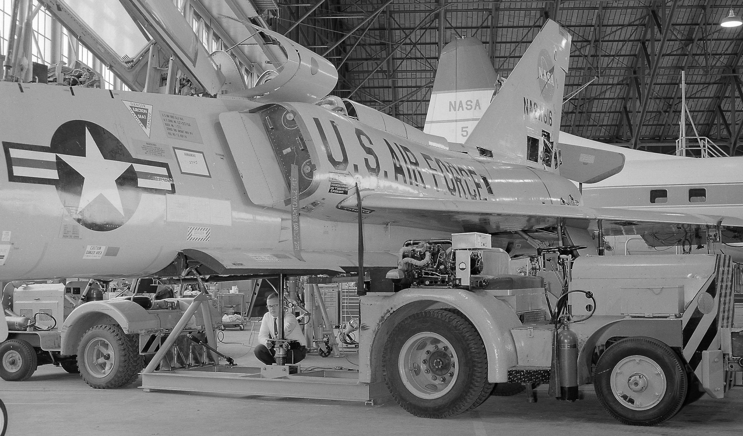
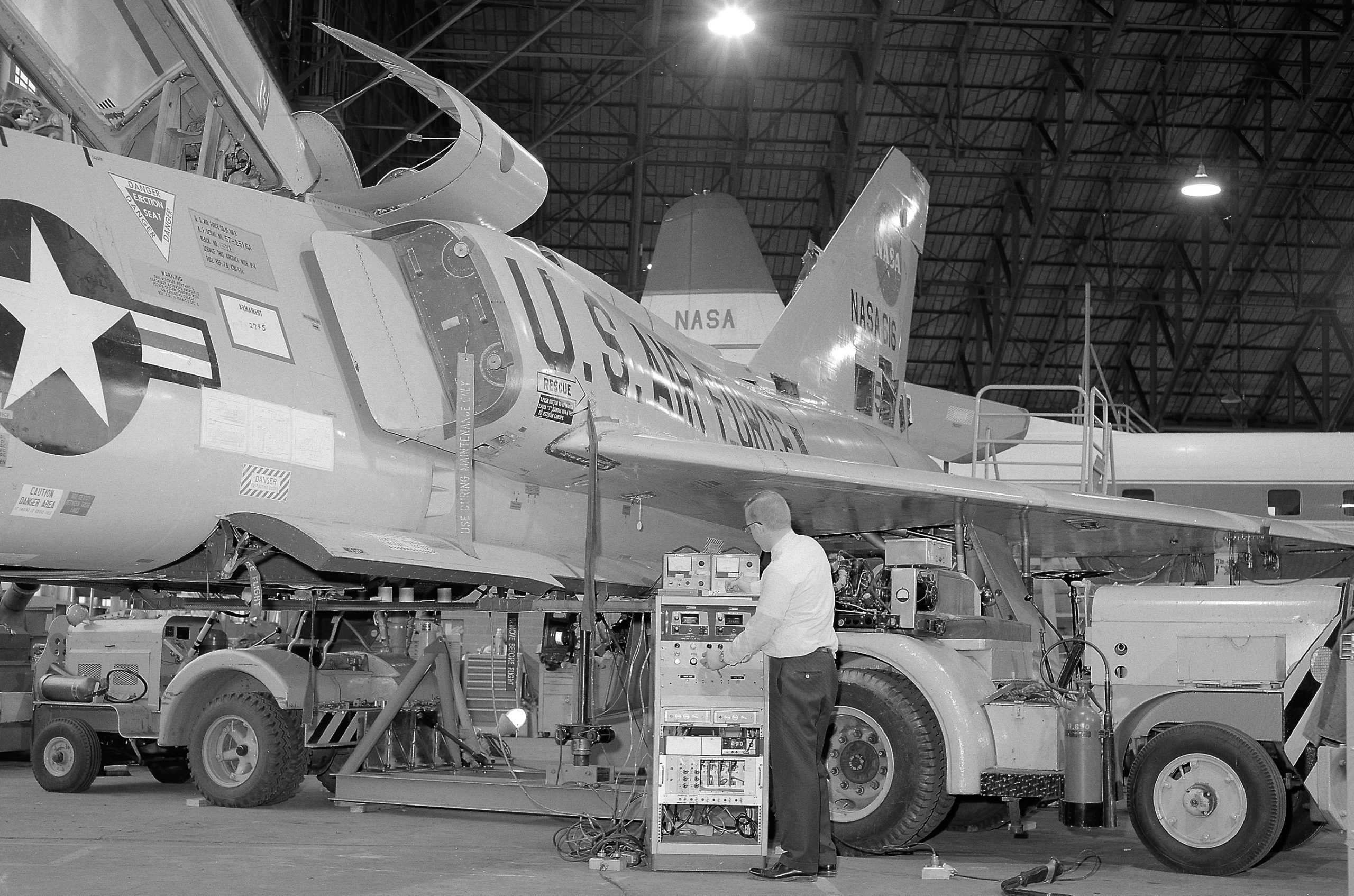
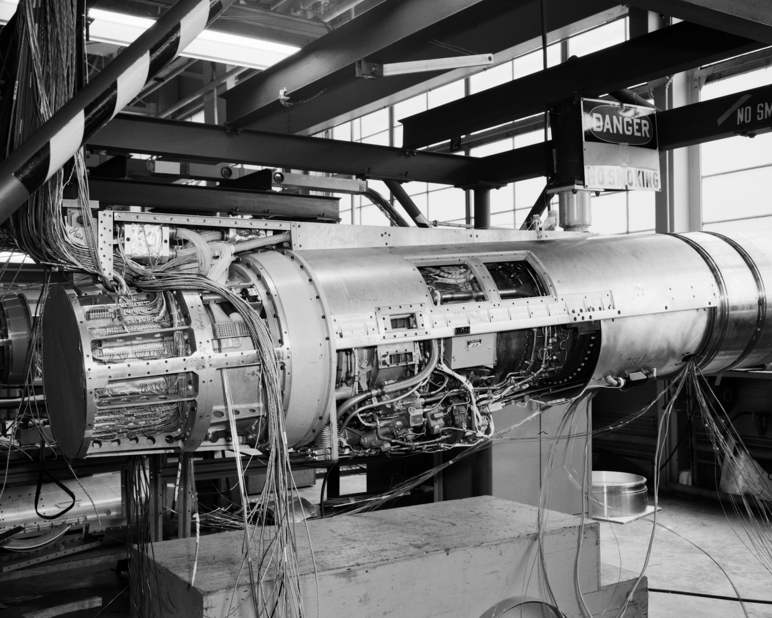
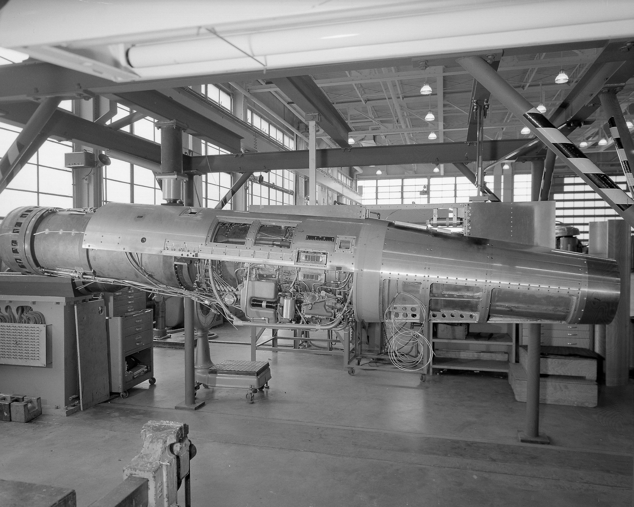
F-106B before the J85 engines were mounted. NASA photo, 1968.
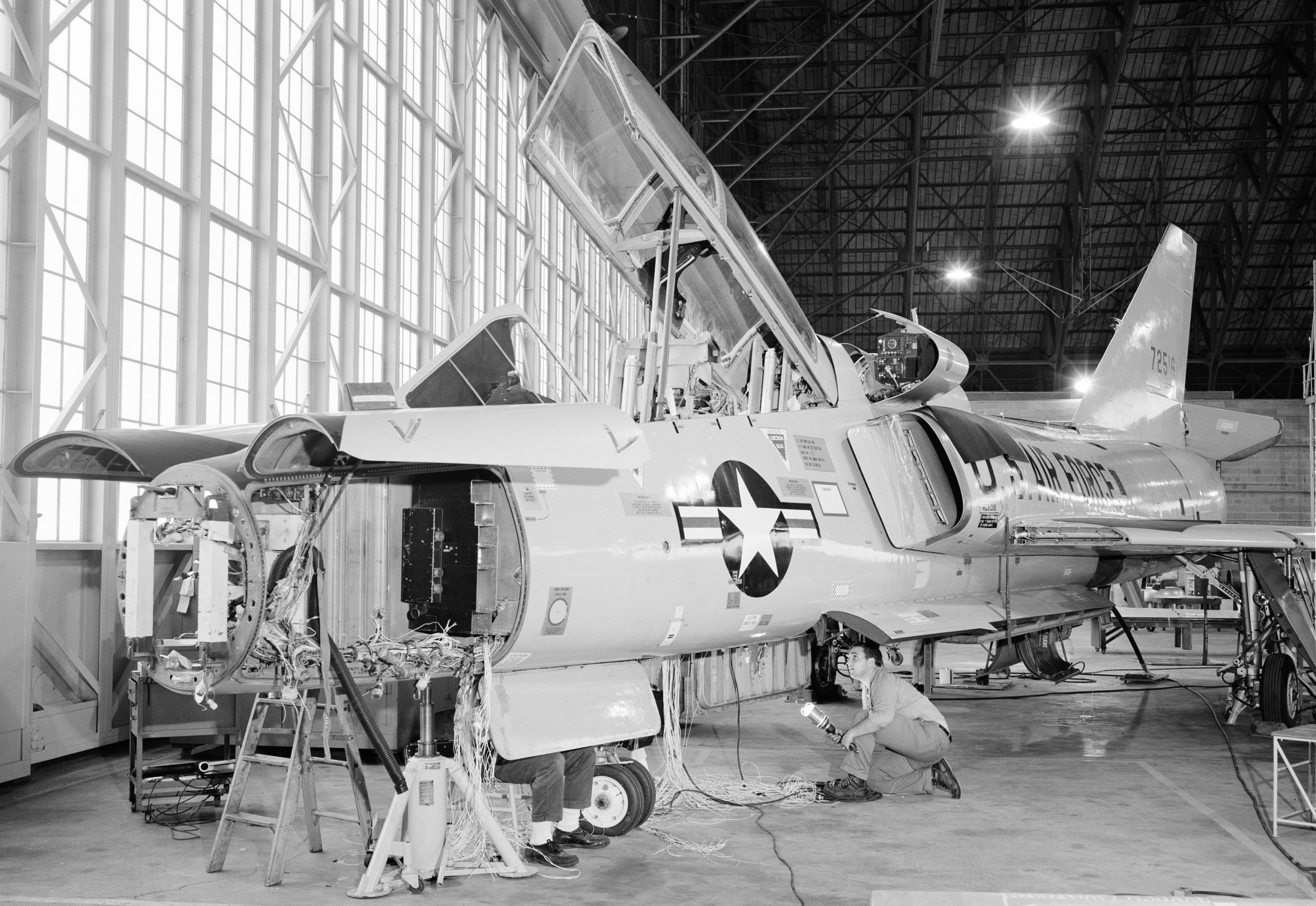
A lot of surgery and load-testing. 2-thousand-5-hundred pounds of weapon system hardware were removed.
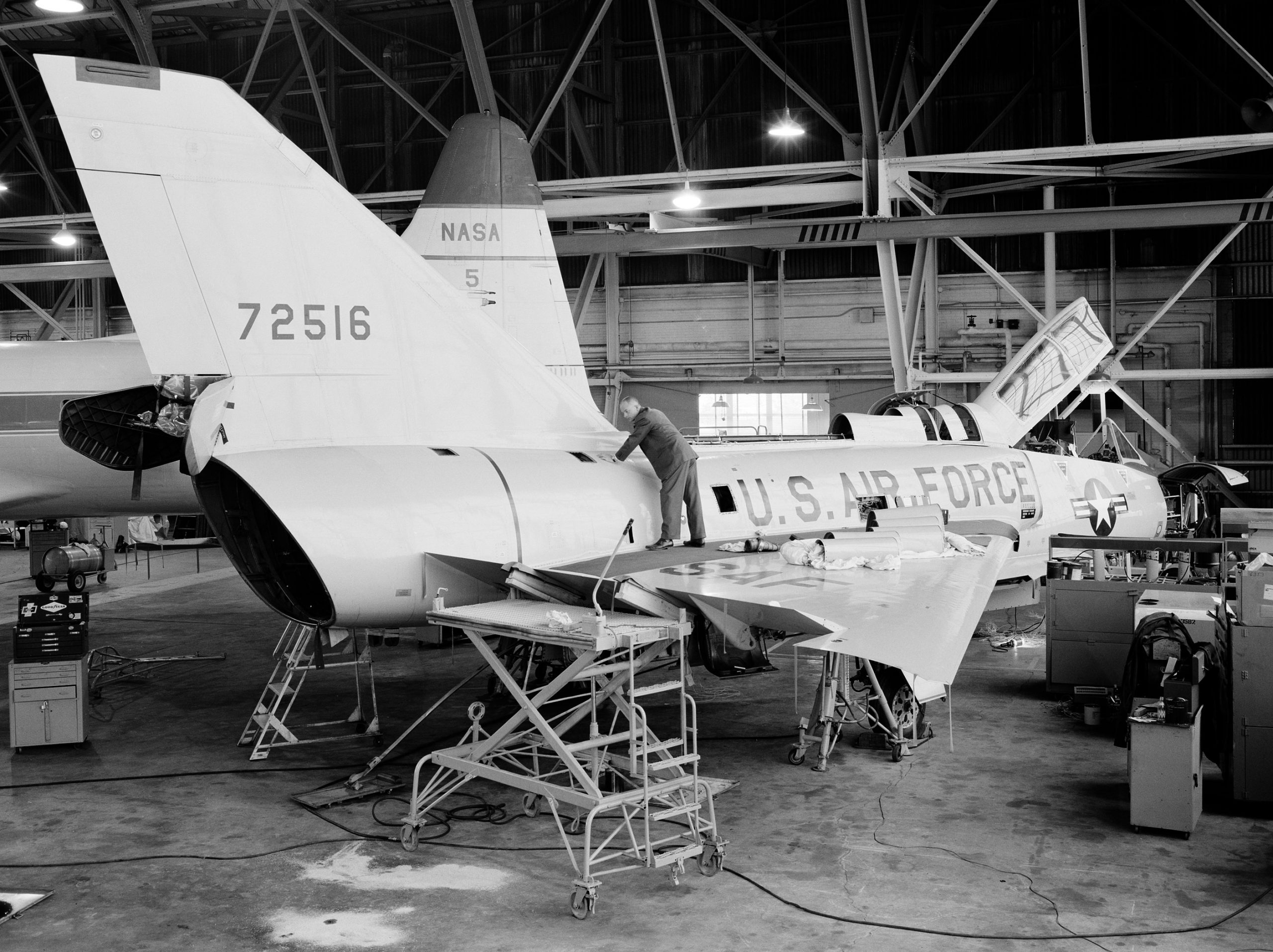
The electrics/wiring was stripped. NASA photo, 1966.
NASA photo, 1966.
Elevon load test, NASA photo, 1967.
NASA photo, 1967.
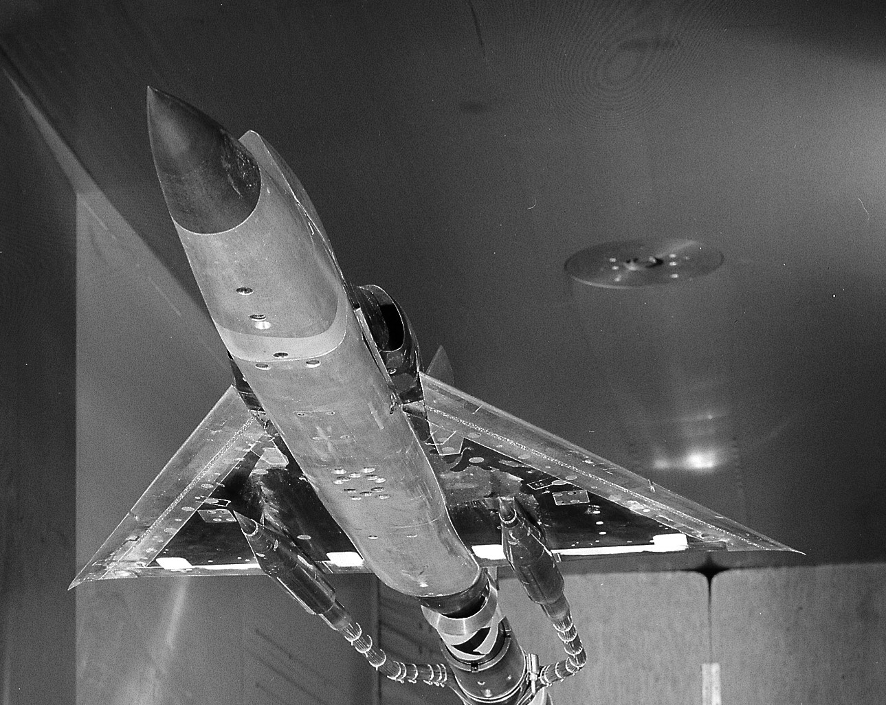
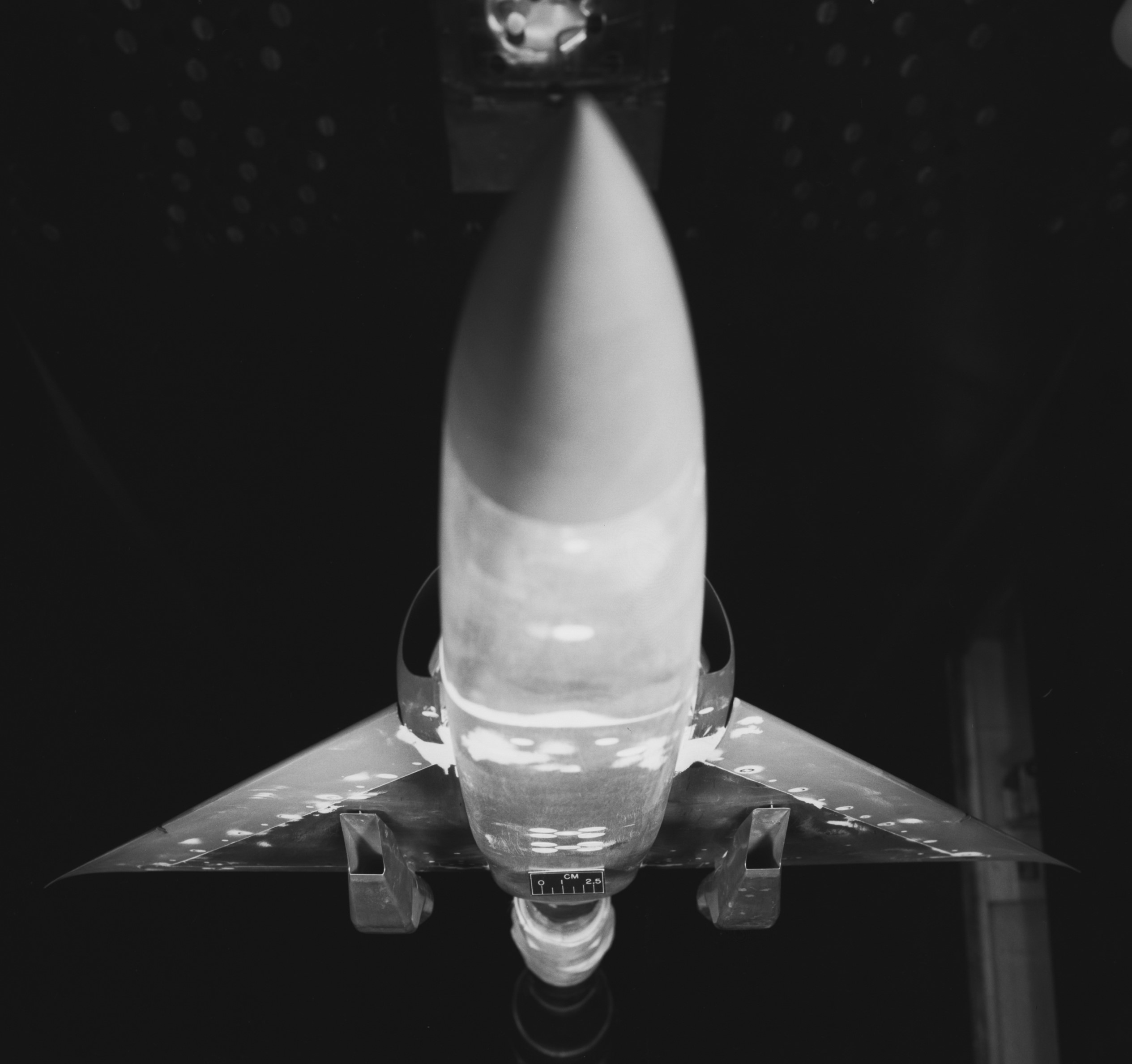
1:20 scale wind tunnel model. NASA photo, 1967.
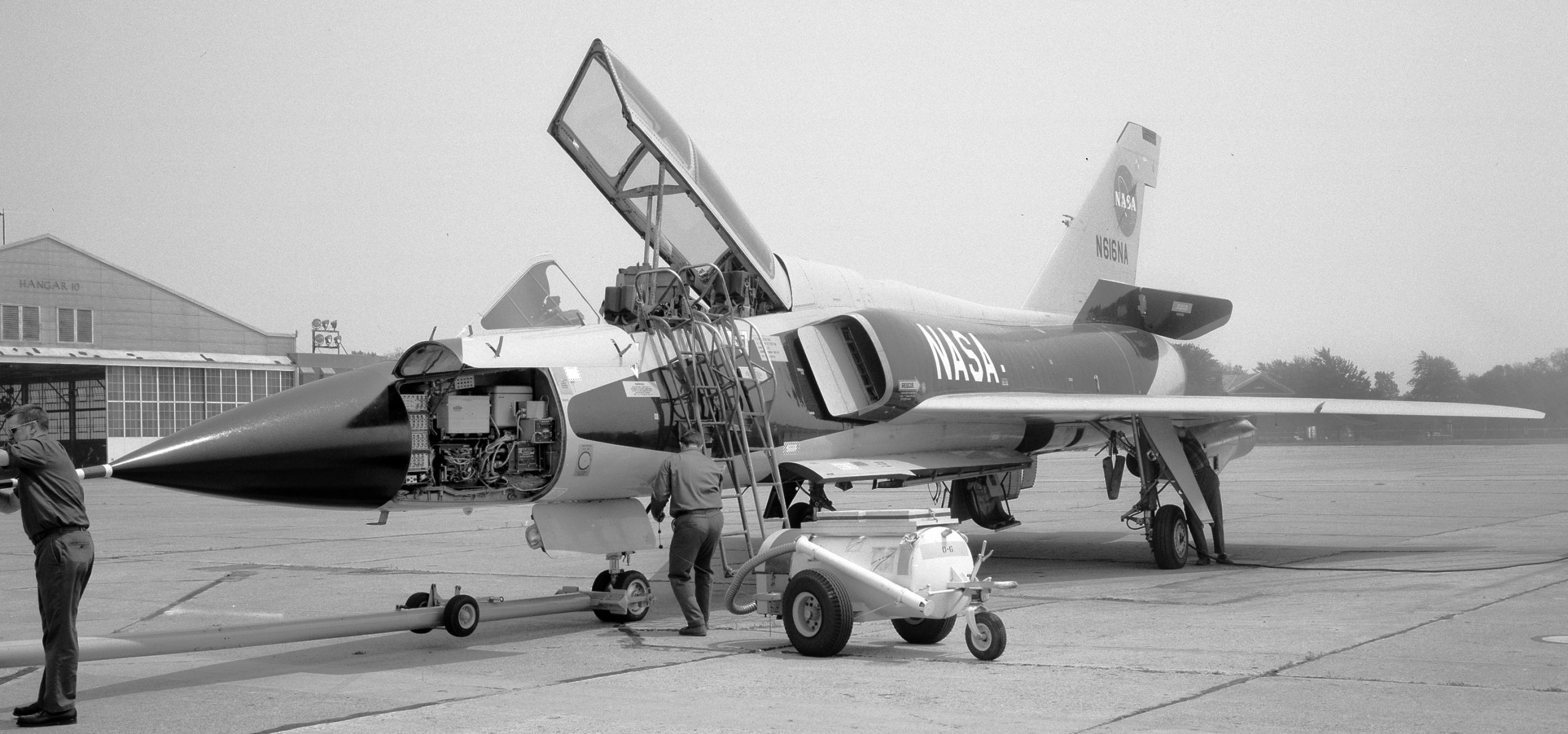
‘616’ after the internal modification, but before the J85 surgery. NASA photo, 1968.
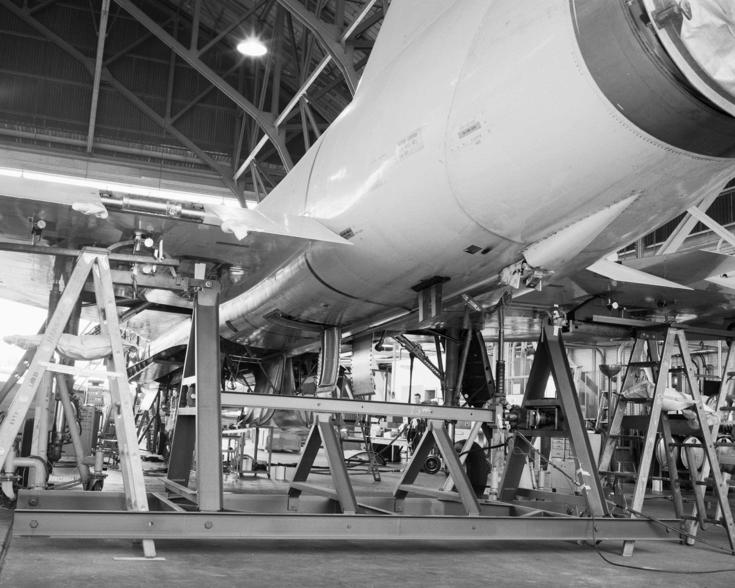
Two aircraft tractors used to manipulate the ‘vertical load tester’ device. NASA photo, 1968.
NASA photo, 1968.
Rear lateral load tester. NASA photo, 1968.
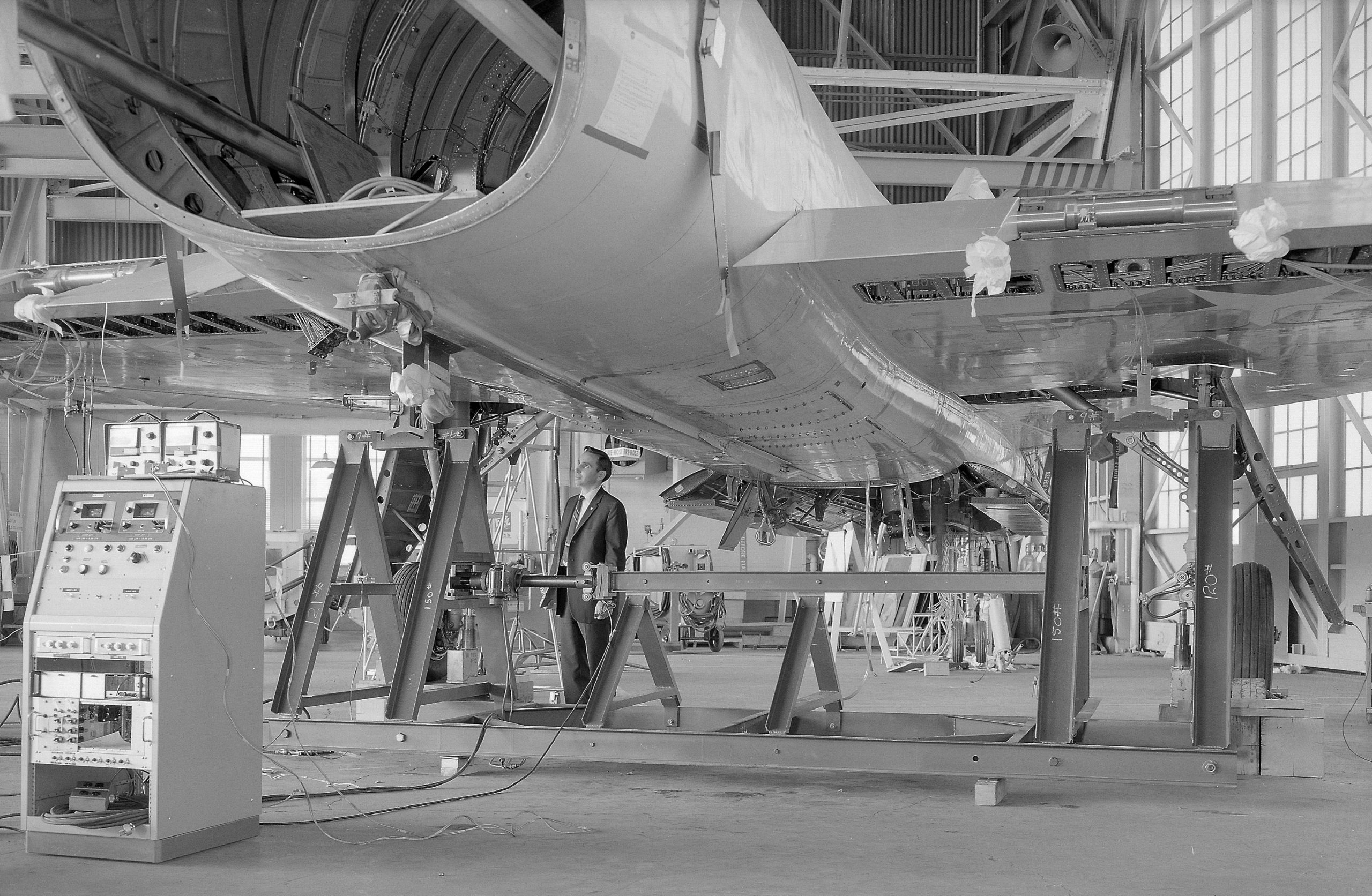
Looking like the rear load tester, NASA claims this is the “front mount side load tester”. NASA photo, 1968.
NASA photo, 1968.
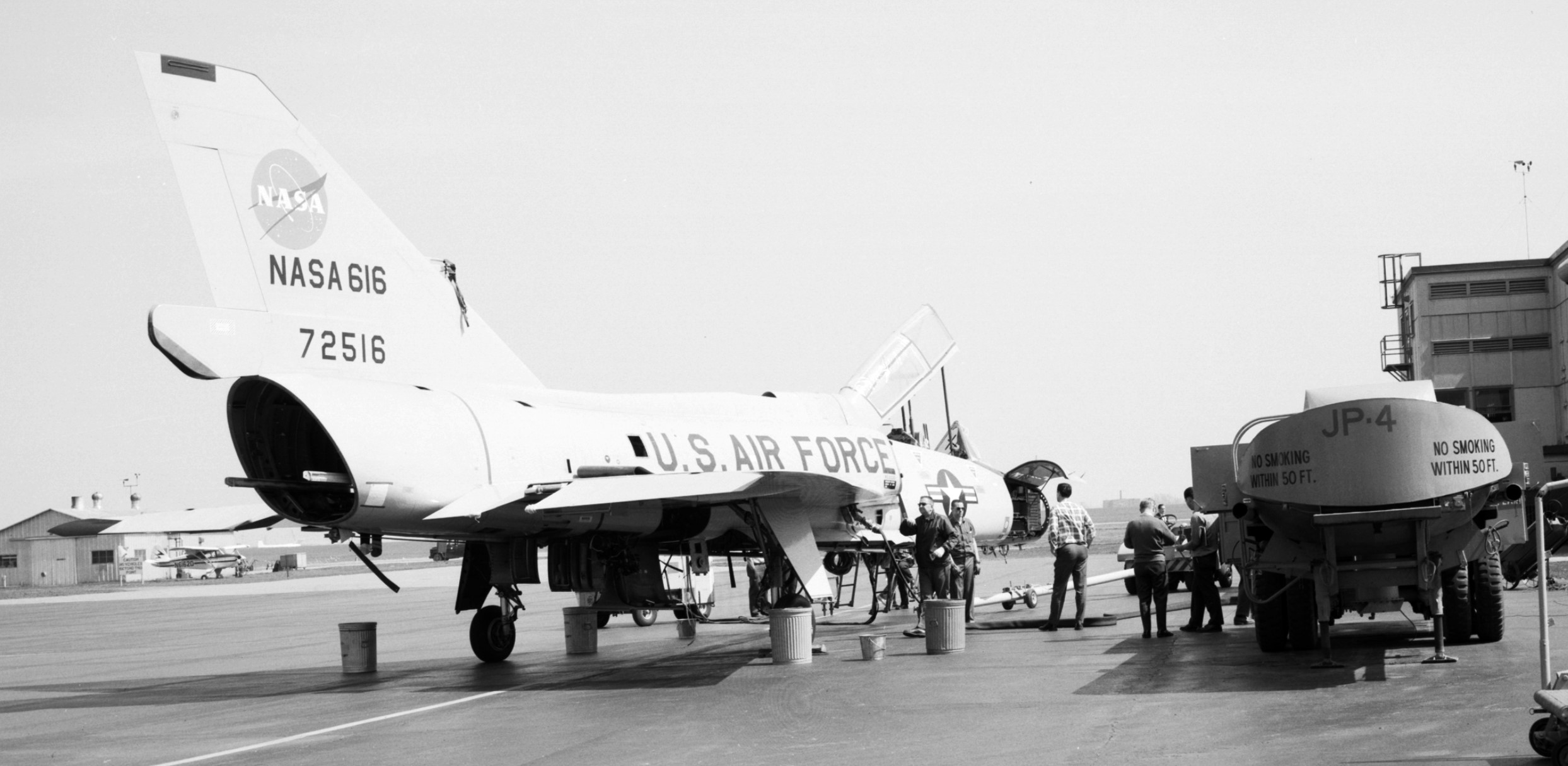
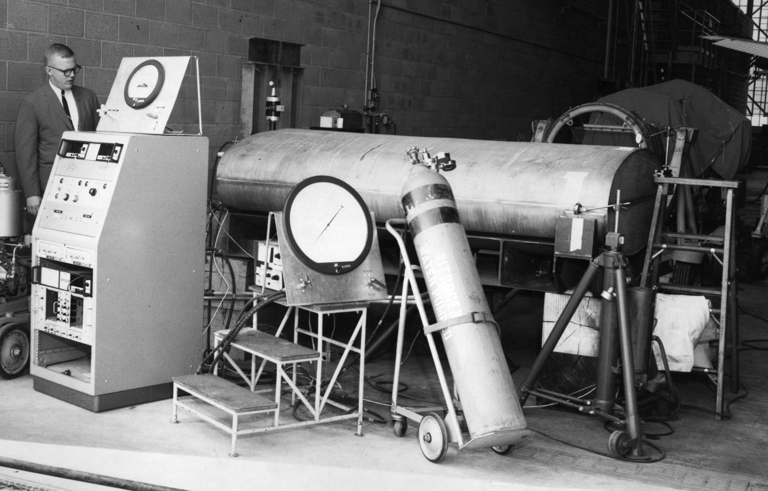
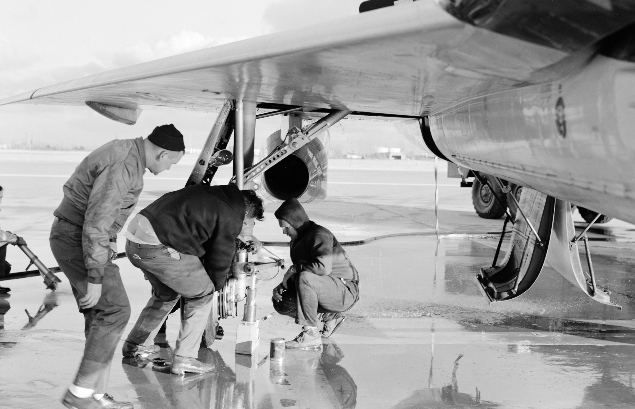
Despite no engines, they were pumping JP-4 (a type of kerosene for jet aircraft), apparently to test the fuel tanks? NASA photo, 1968.
NASA photo, 1968.
NASA photo, 1968.
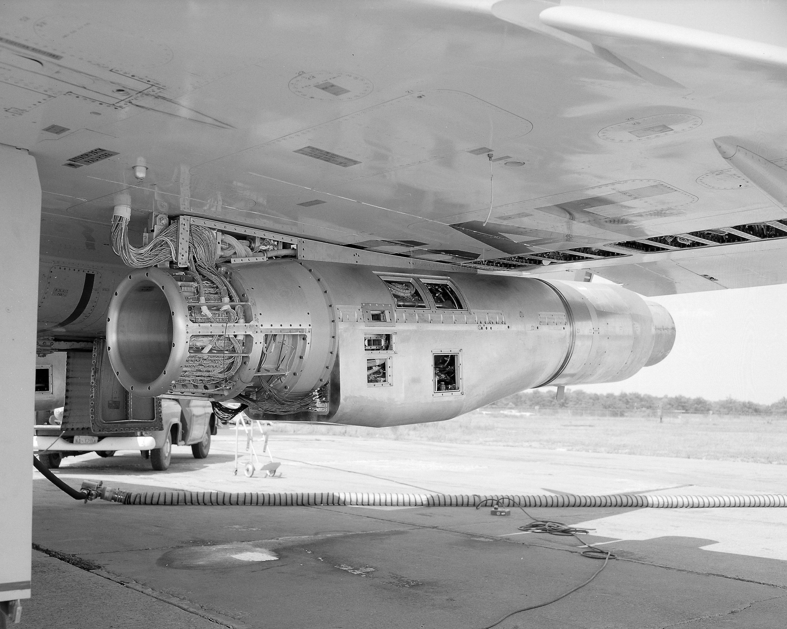
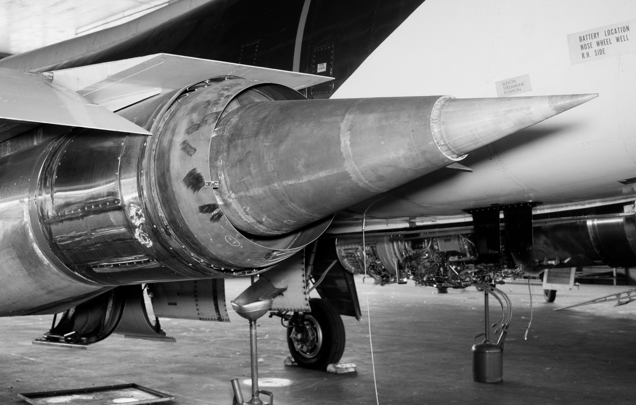
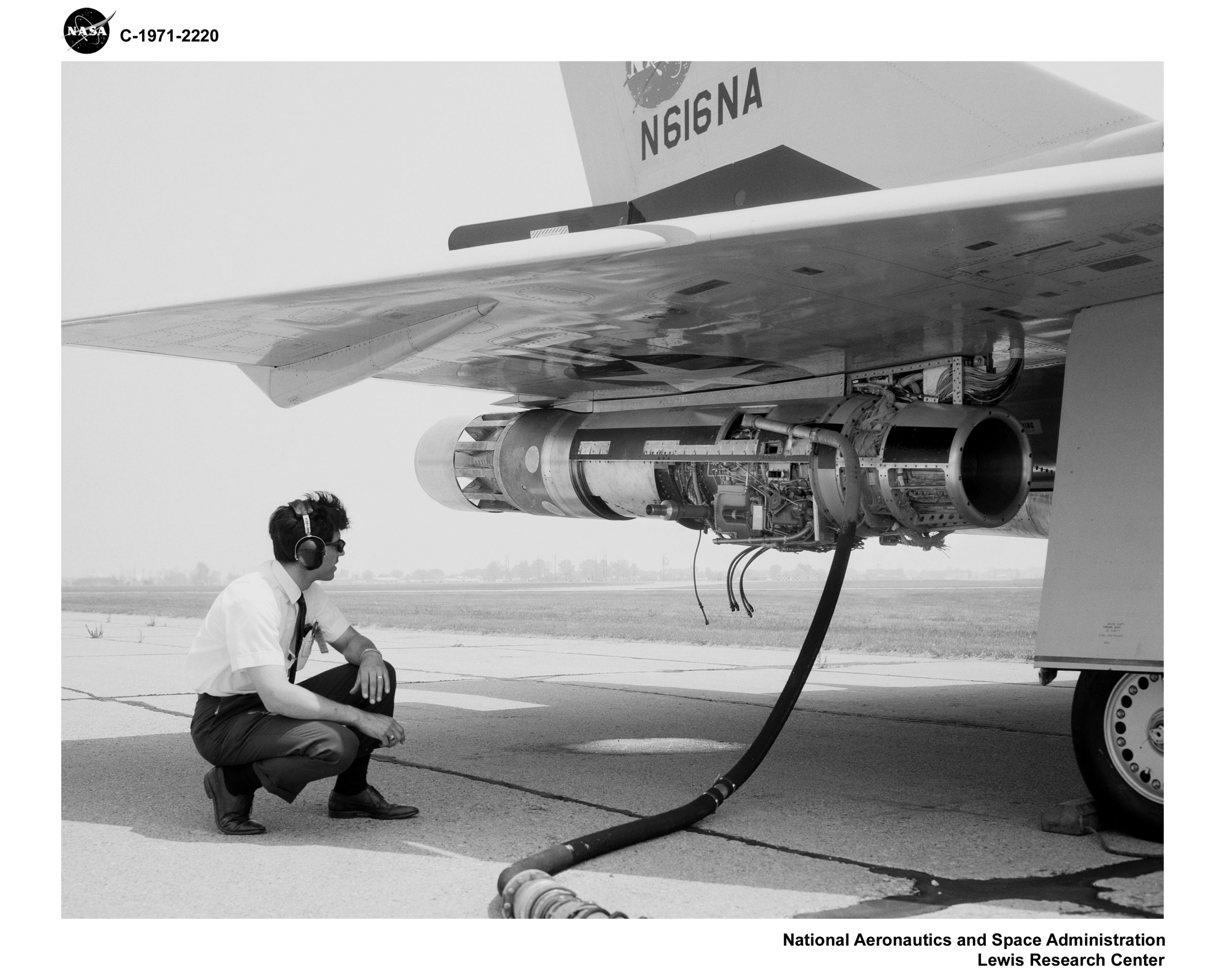
Underwing nacelle. The first research flight with the three engines was on 03JUN1968.
NASA photo, 1968.
NASA photo, 1968.
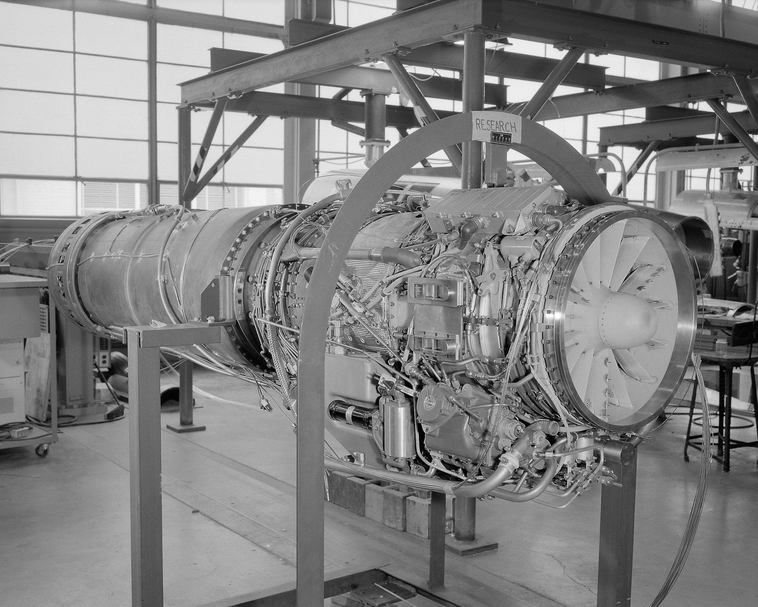
General Electric J-85 engine. The J85 was originally designed for a air-to-surface missile carried by the B-52, but it went on to power the T-38, F-5, A-37 and CT-114.
NASA photo, 1968.
Nacelle build-up. Apparently the left (port, #2) engine was a special version of the J85, and the right (starboard, #3) engine was the standard production J85. The idea was to use the experimental things on the ‘special’ J85 and then compare the performance to the ‘normal’ J85.
NASA photo, 1968.
Interior of J85 nacelle. NASA photo, 1968.
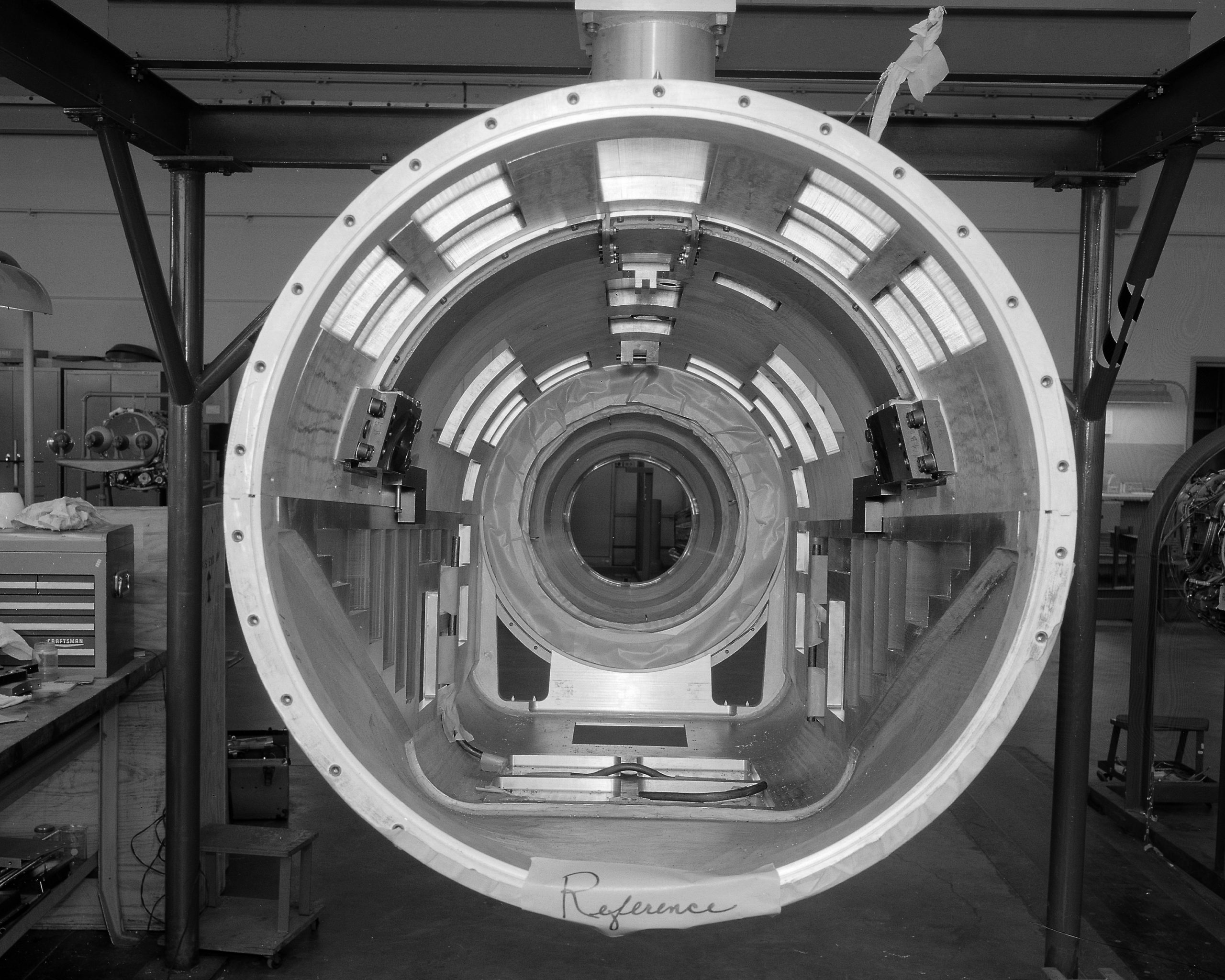
Aft missile bay fuel tank. NASA photo, 1968.
A new fuel tank was made to fit the internal weapons bay.
NASA photo, 1971.
NASA photo, 1976.
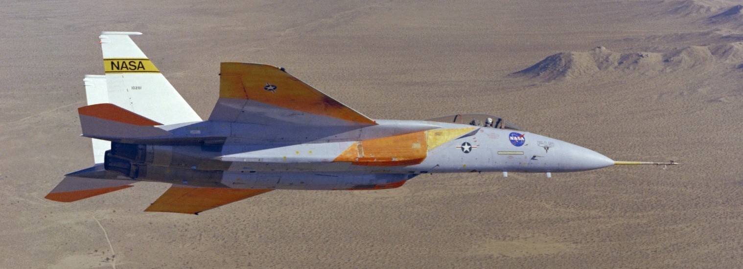
Note three jet exhausts on the F-106B. The co-pilot in the rear seat operated the J85 engines.
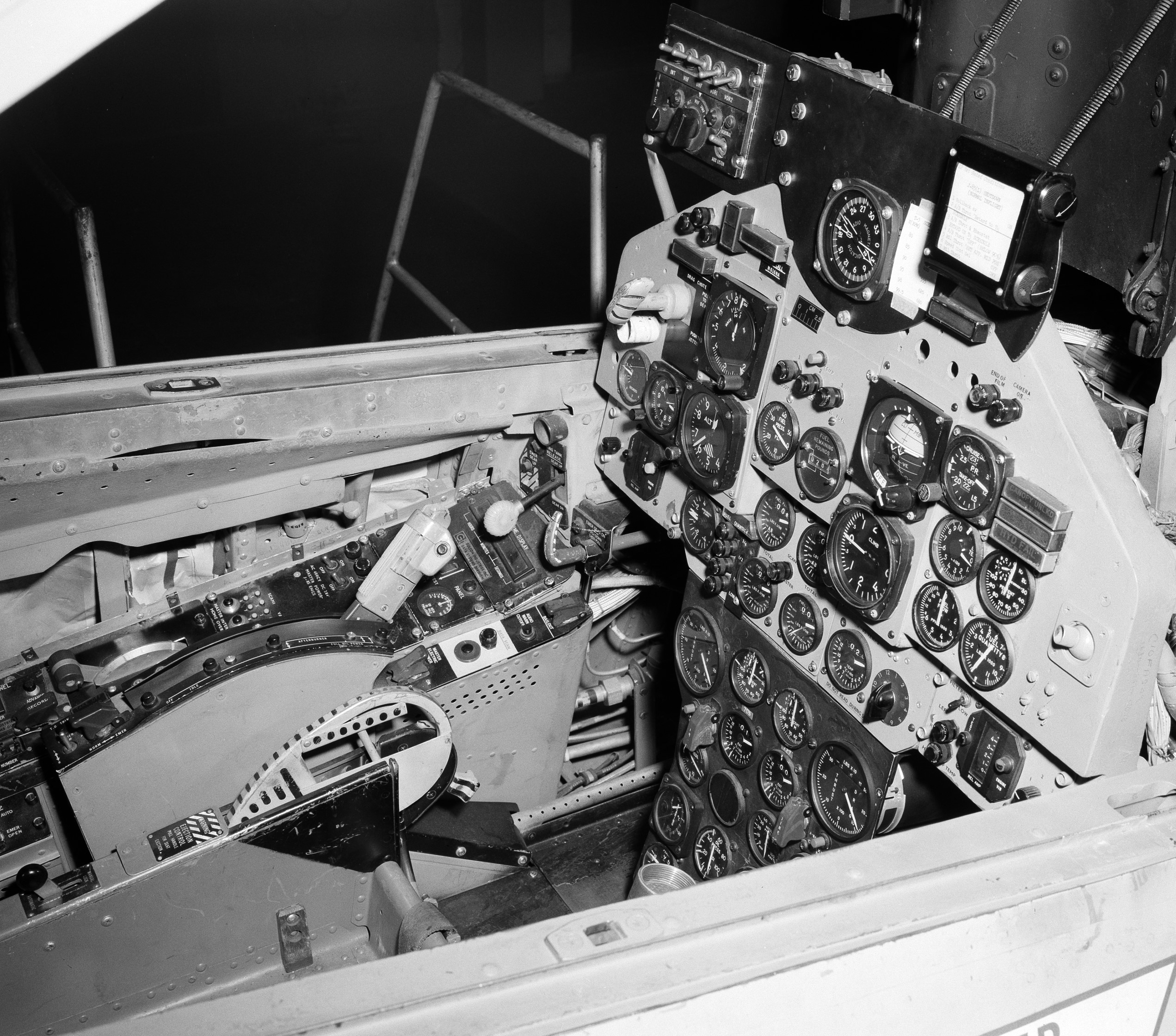
NASA says this photo shows the rear seat throttle controls for the two J85 engines.

NASA photo, 1968.
NASA tried different sensors.
NASA photo, 1974.
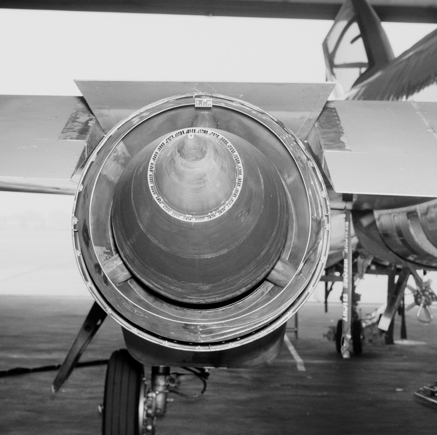
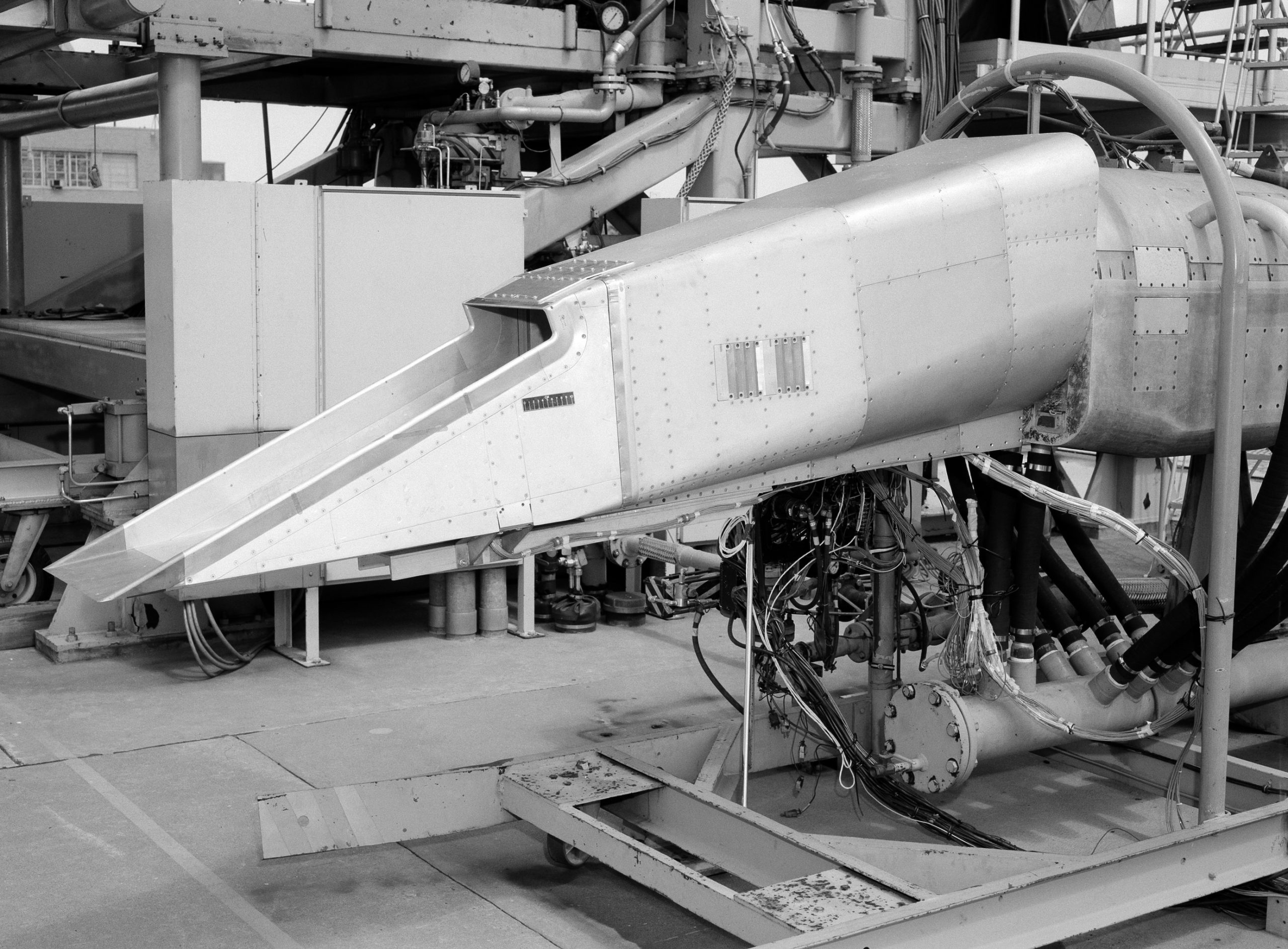
The U.S. Air Force wanted to test different types of exhaust nozzles in an attempt to achieve supersonic cruising (without using the after burner).
NASA photo, 1969.
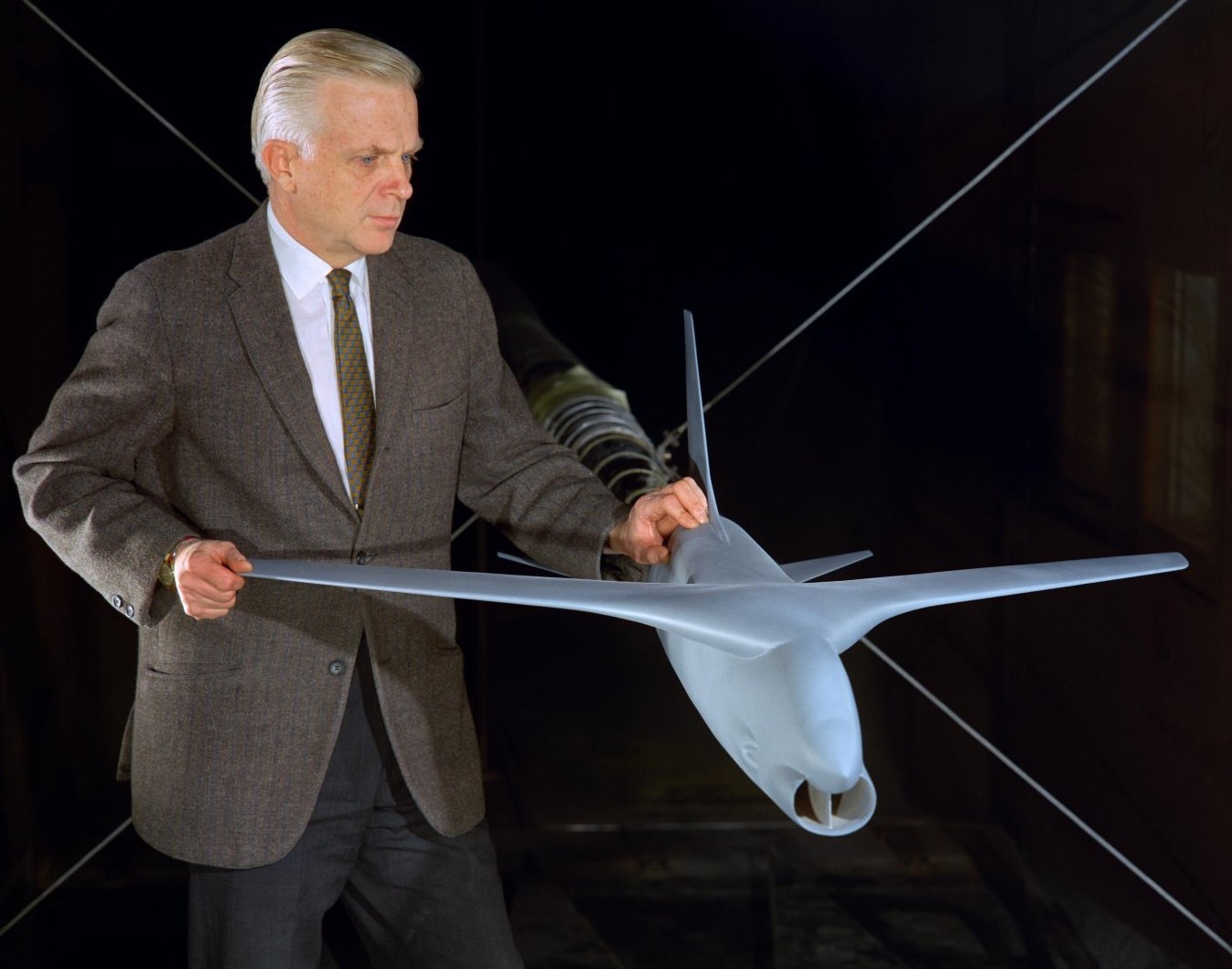
The U.S. commercial passenger airliner industry also wanted to test ideas for the Super Sonic Transport (SST). Boeing/General Electric/NASA’s first attempt at an SST was canceled in 1970 when the U.S. Senate refused to spend anymore tax dollars on it. Another attempt was made in the 1990s when NASA/Boeing began using a modified Russian SST, that program was also canceled due to lack of funding.
NASA photo, 1971.
NASA photo, 1971.
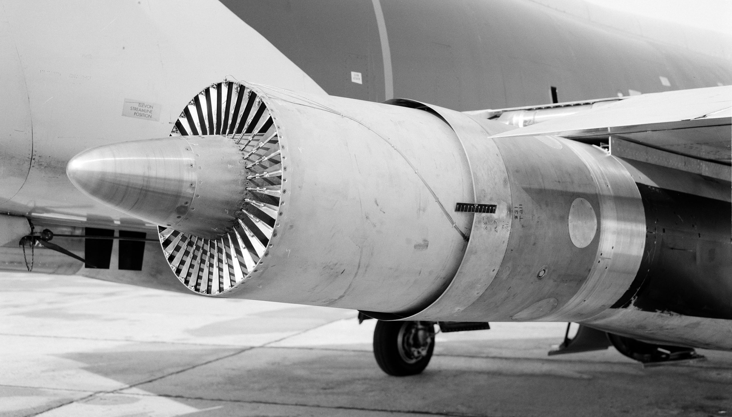
General Electric 32 spoke fan nozzle. NASA photo, 1971.
Silent video of multi-engined F-106B ‘616’ roll-out, take-off, flight and landing. This edit also includes lightning strike testing, NASA ‘816’ (formerly 616) was also ‘lightning hardened’ and intentionally flown into thunderstorms. That testing helped develop technologies that are taken for granted today:
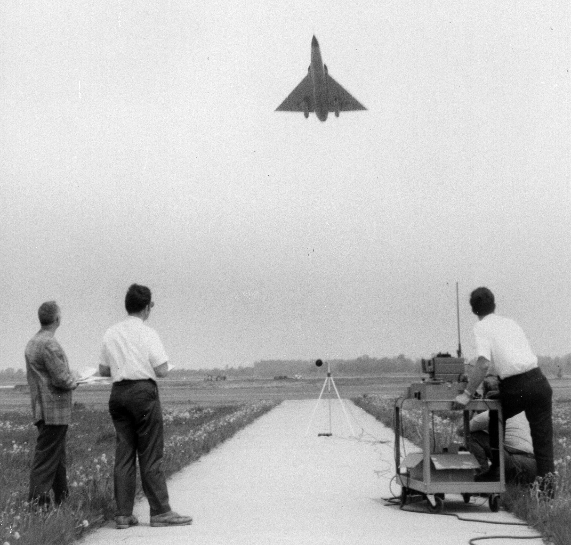
Sound check. NASA photo, 1970.
It was also used to test jet engine mufflers (acoustic suppressors) for the U.S. airliner industry. This is because taxpayers had successfully got their lawmakers to limit the level of noise created by jet airliners. Unfortunately, all attempts to suppress the noise levels of jet engines had no affect on preventing sonic booms, and many global metro areas (the only markets for SSTs) made it a crime to break the sound barrier, just one of many reasons why SSTs like Concorde and Tu-114 were killed off.
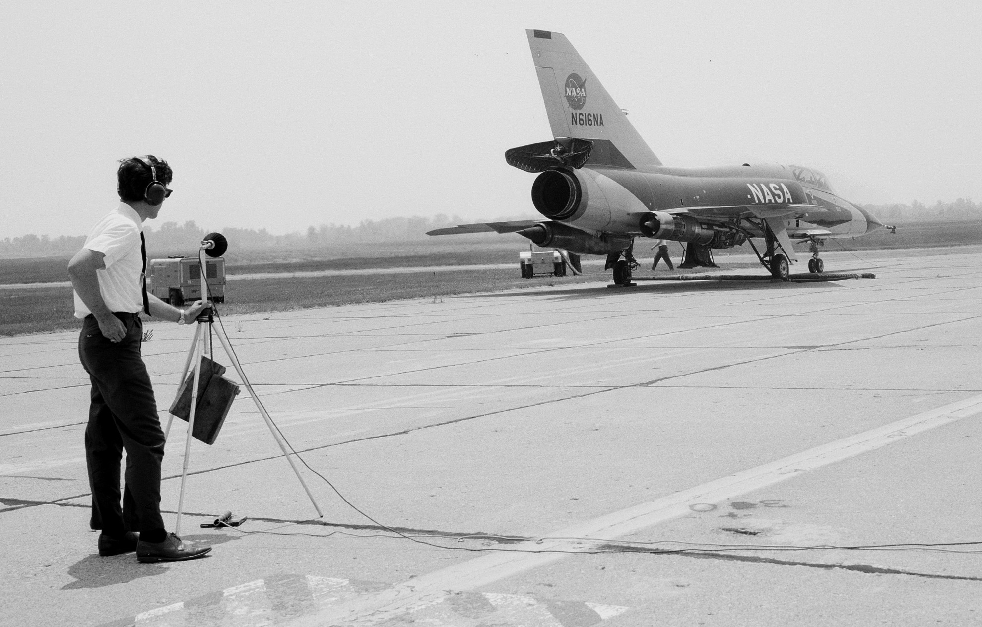
This is how NASA does a ‘mic check’. NASA photo, 1971.
‘Acoustic Plug & Shroud’ testing. NASA photo, 1971.
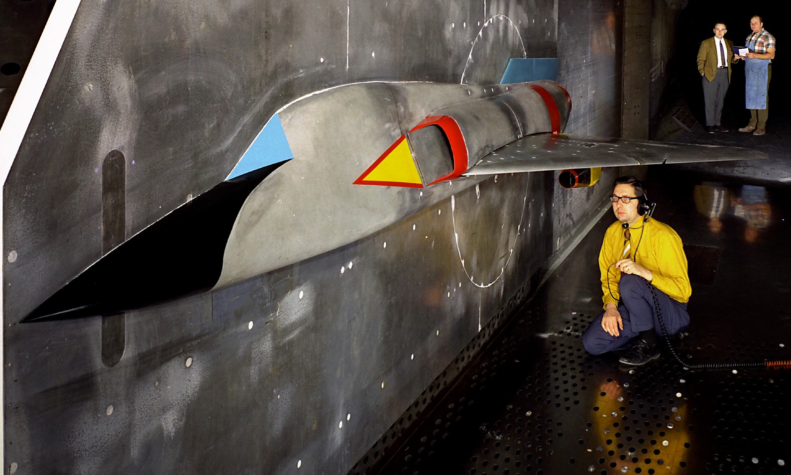
Half span wind tunnel model. NASA photo, 1971.
NASA photo, 1971.
Wind tunnel model with squared ‘wedge’ F-15 style intakes.
Installing a F-15 style intake on a J85 nacelle. NASA photo, 1975.
NASA photo, 1971.
Blown main-gear tire at Selfridge Air Force Base, Michigan, 1971.
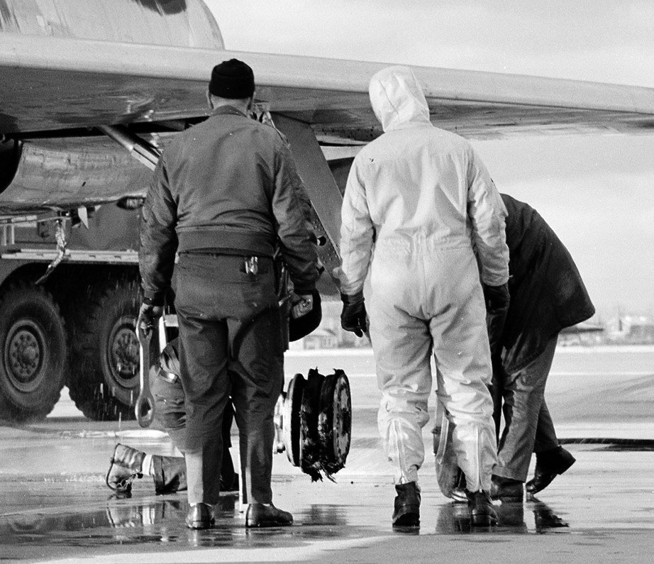
NASA photo, 1971.
About to take a final flight. NASA photo, 1977.
Supposedly this is a photo from the final flight of the three engined F-106B. It would return to having just one engine.
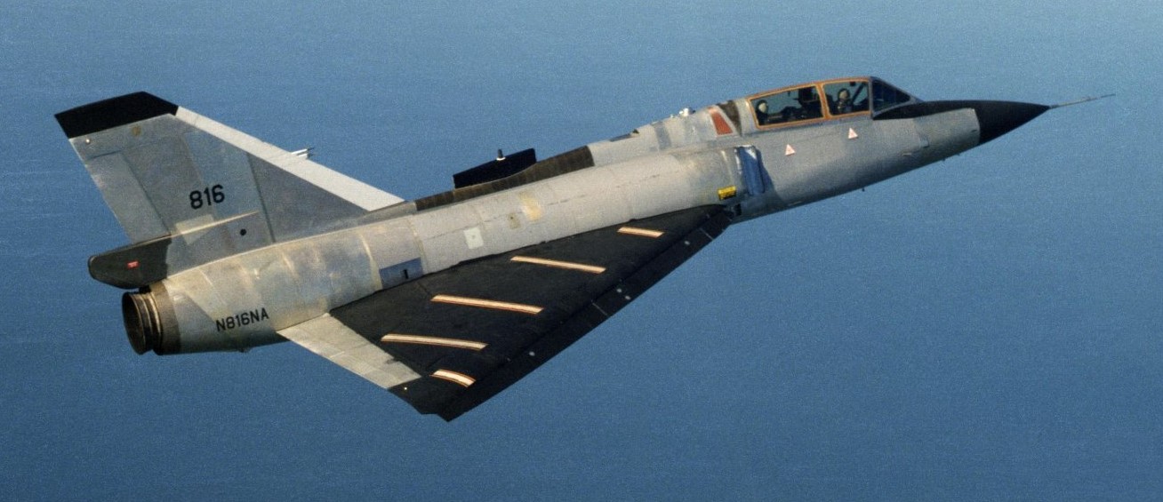
‘616’ to ‘816’. NASA photo, February 1990.
In 1979, NASA 616 was sent to Langley Research Center where it became 816. As the last piloted Convair F-106 anywhere, NASA 816 saw service at Langley researching storm hazards, experimenting with an ‘Off-Surface’ flow visualization system, and testing a vortex flap.
F-106B NASA 616(816) was retired in May 1991:“NASA 816 made its last flight on April 30. It was the last known piloted Convair F-106 still flying.”
Supposedly, 616/816 was not turned over for target drone duty as were the vast majority of F-106s, but retired to the Virginia Air & Space Center in Hampton, Virginia.
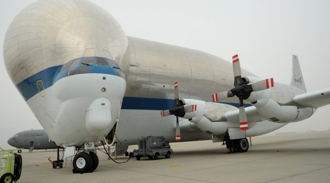
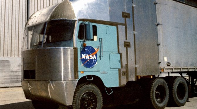
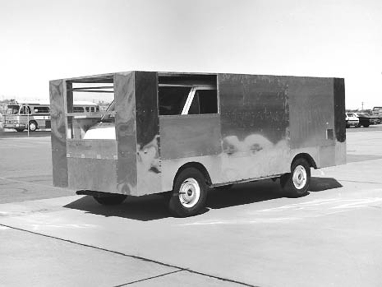
Bare Metal: NASA Trucks
Taxpayers help the Airliner Industry: NASA’s Tupolev 144 SST
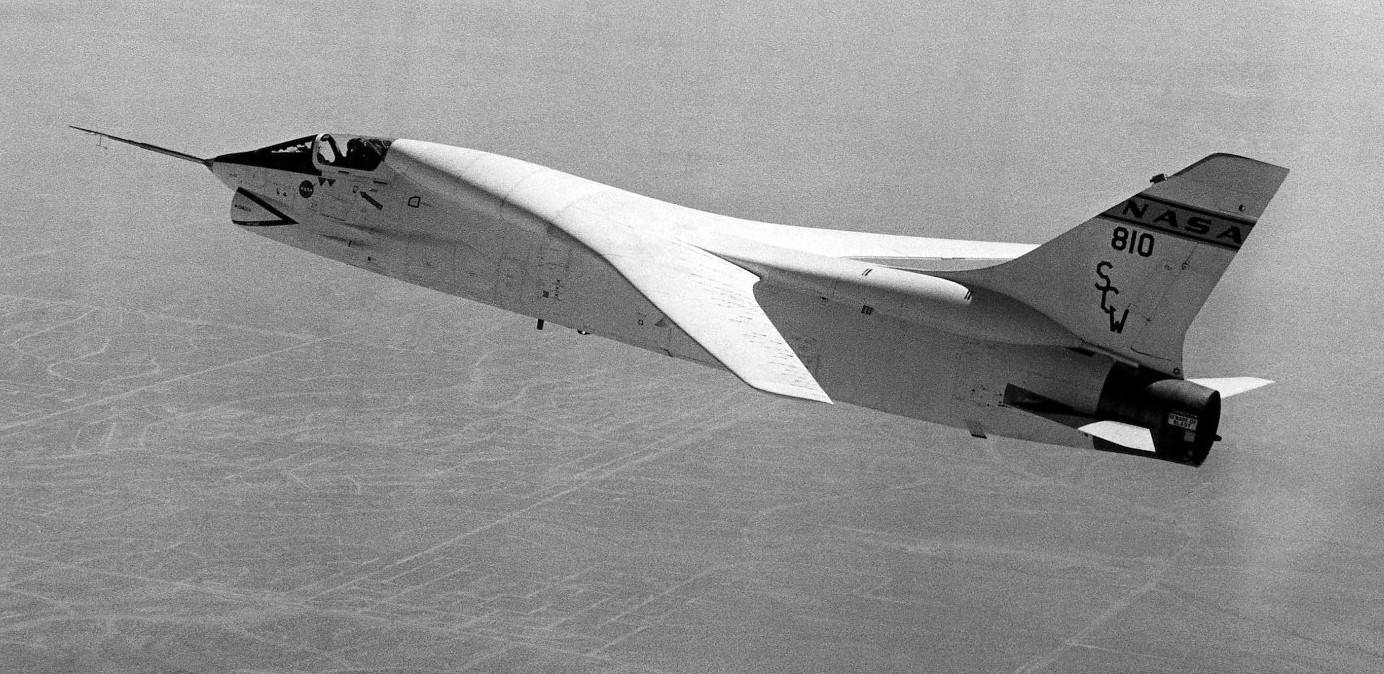
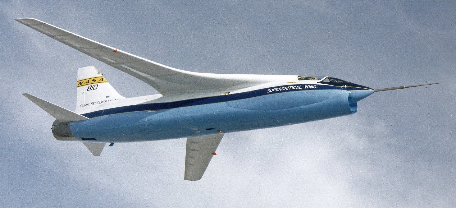
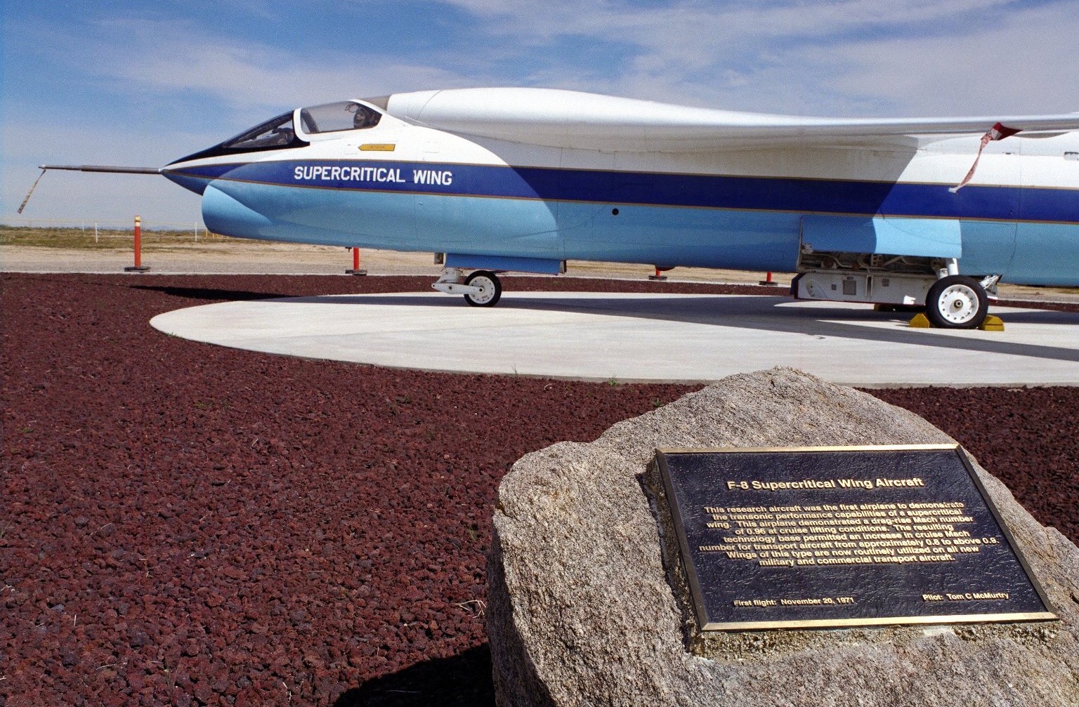
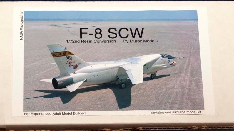
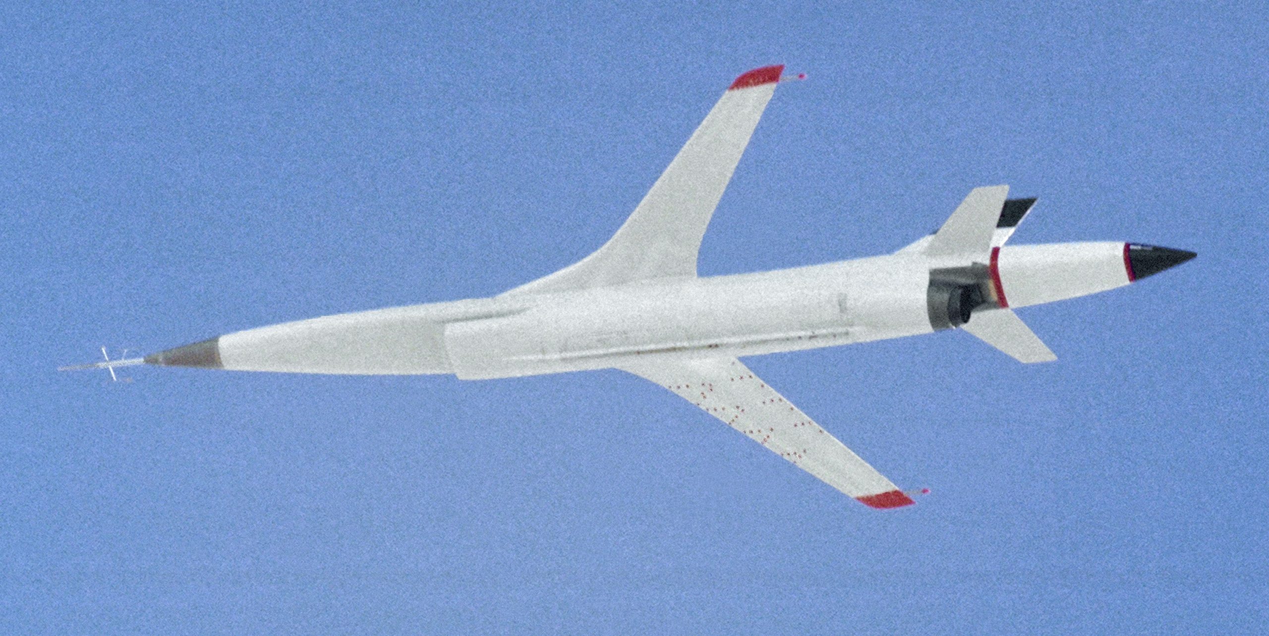
Vehicle I-D: NASA’s F-8 SUPER-CRITICAL-CRUSADER, FATHER OF MODERN AIRLINER WING DESIGN


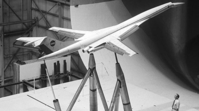


 However a reduced scale model of the Full Scale Wind Tunnel was also built: “The excellent energy ratio obtained in the new wind tunnel of the California Institute of Technology suggests that before proceeding with our full scale tunnel design, we ought to investigate the effect on energy ratio of such factors as: 1. Small included angle for the exit cone; 2. Carefully designed return passages of circular section as far as possible, without sudden changes in cross sections; 3. Tightness of walls. It is believed that much useful information can be obtained by building a model of about 1/16 scale, that is, having a closed throat of 2 ft. by 4 ft. The outside dimensions would be about 12 ft. by 25 ft. in plan and the height 4 ft. Two propellers will be required about 28 in. in diameter, each to be driven by direct current motor at a maximum speed of 4500 R.P.M. Provision can be made for altering the length of certain portions, particularly the exit cone, and possibly for the application of boundary layer control in order to effect satisfactory air flow. This model can be constructed in a comparatively short time, using 2 by 4 framing with matched sheathing inside, and where circular sections are desired they can be obtained by nailing sheet metal to wooden ribs, which can be cut on the band saw. It is estimated that three months will be required for the construction and testing of such a model and that the cost will be approximately three thousand dollars, one thousand dollars of which will be for the motors. No suitable location appears to exist in any of our present buildings, and it may be necessary to build it outside and cover it with a roof.”-Elton W. Miller, 26JUN1929


 MX-334 flying wing glider, 1943.
 Bell XP-77 1:1 scale model, 1943.
 Mercury space capsule, January 1959.
 Testing the proposed parawing landing system for space capsules.

 Testing one of the proposed Lunar Excursion Module (LEM) models.


 In 1999, NASA (National Aeronautics Space Administration) decided to test a 1:1 scale model of the Wright Flyer, for aerodynamic data. However, the full-scale Wright Flyer was built stronger than the original for fear it wouldn’t hold up in the wind tunnel (it was tested at only 30mph/48kmh).
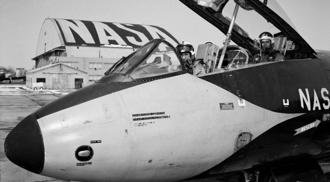
 This NASA B-57B was used to test the jet engine ‘mufflers’ (aka
  Wright J65-W-5 turbojets power the B-57B.
 Note the tail support rod, yes, even real jet aircraft used tail supports when parked for a long time. Also, the Hush Kits added a lot of weight to the rear of center-of-balance.
 According to the information with this NASA photo the aircraft was painted in fluorescent colors, but it didn’t specify. They probably meant Day-Glo, which is the copyrighted name of the
  09DEC1971, tail code 809 is bare metal with NASA markings and a ‘V’ under the cockpit. The V stood for Viking Mars Lander parachute test program.
 11 years later, tail code 809 in the standard white with blue stripes NASA colors. Wing tip pitots (both sides), different nose tip and pitot. In 1982, 809 began atmospheric research, everything from wind currents to air pollution.
 809 was retired in 1987.
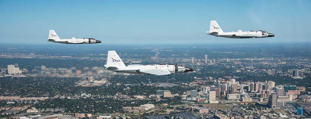
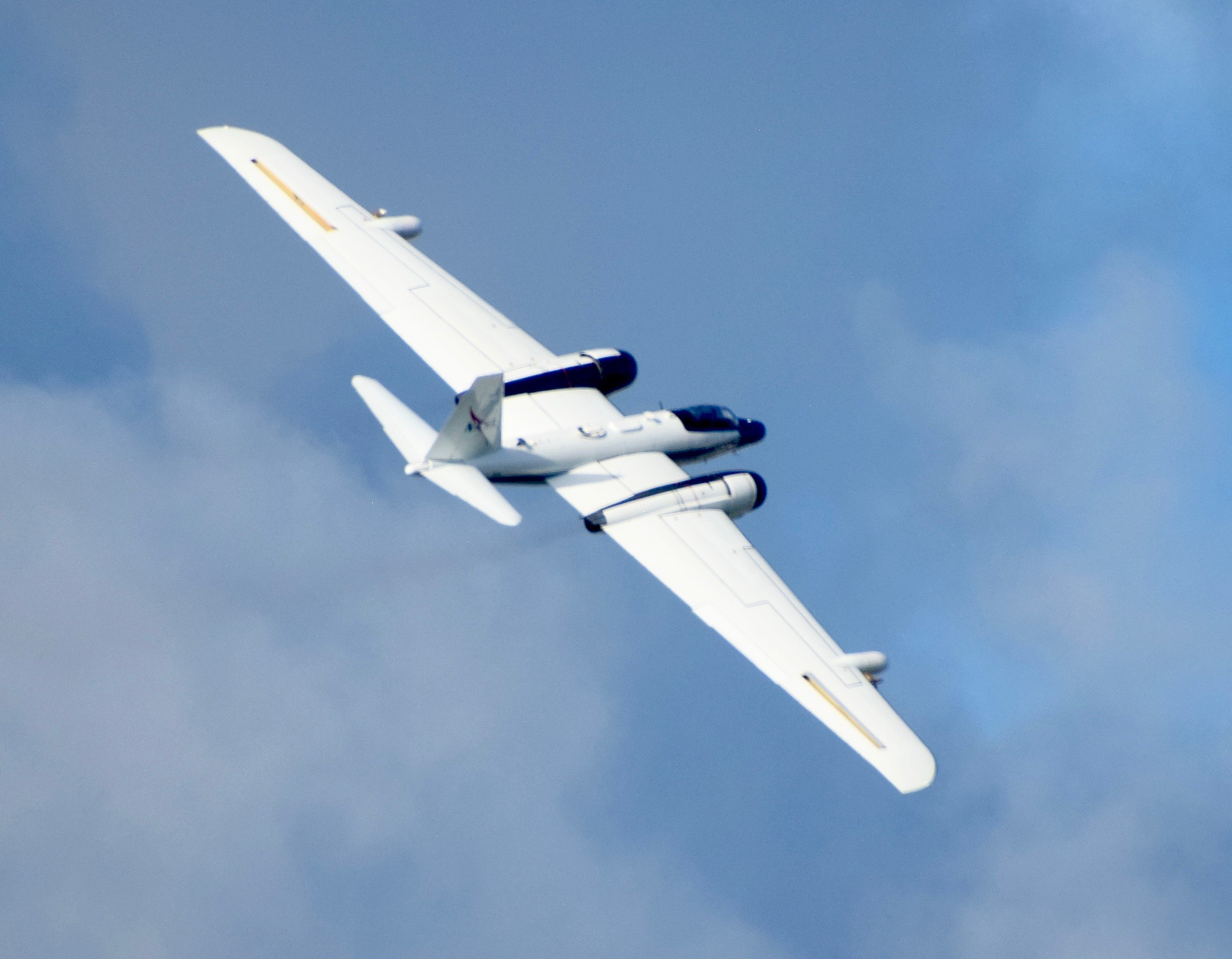
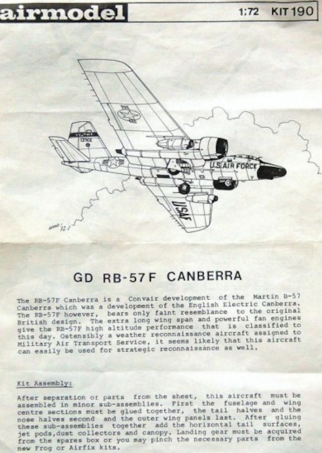
 The U.S. Air Force RB-57F was developed in the early 1960s to take air samples over enemy countries to determine if they had conducted nuclear bomb experiments. However, that was the secret mission, the official mission of RB-57Fs was weather forecasting. USAF RB-57Fs were plagued by engine problems and structural failures. The engines used are Pratt & Whitney TF33-P-11A turbofans. In 1968 RB-57Fs were re-designated WB-57F.

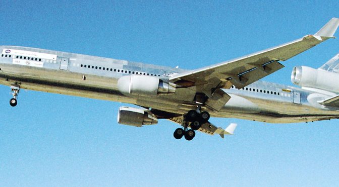
 A NASA WB-57 takes off from the flight line of Marine Corps Air Station Miramar, California, 21AUG2019. The aircraft was utilizing the MCAS Miramar flight line and airspace to test new communications software.
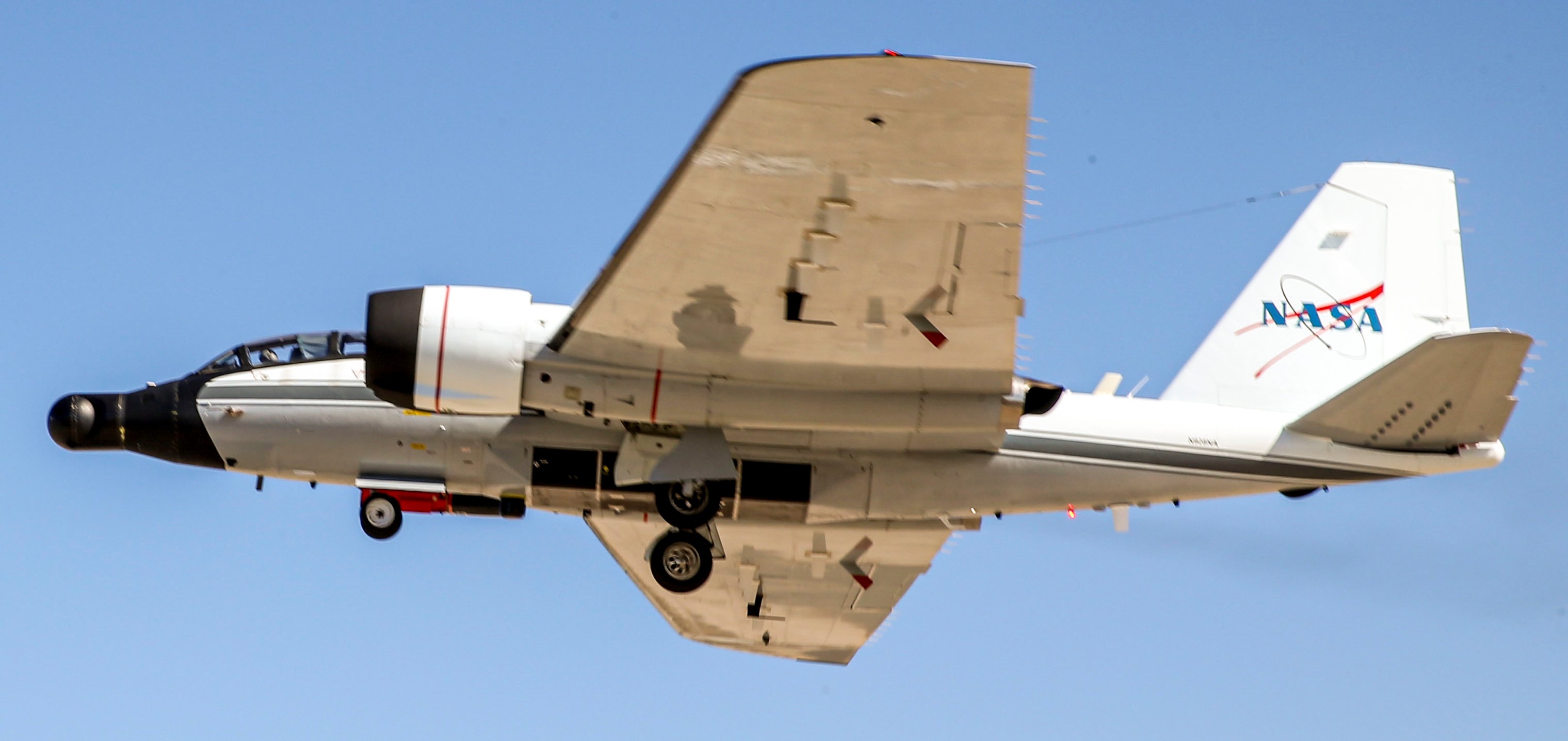


 In the rear seat (Robins AFB, Georgia), Don Darrow is about to take-off on a mission to track Hurricane Joaquin, in 2015.
 Spain, 2011, stop-over for routine maintenance and refueling.

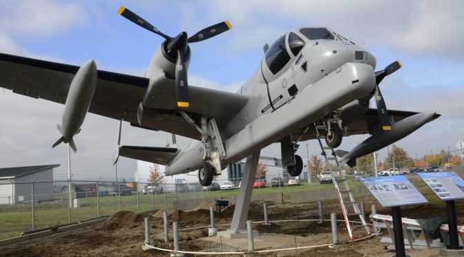
 Oregon National Guard’s Project 926, move the old tail number 926 OV-1C Mohawk ‘gate guard’ to a better location.


 23OCT2019 was the culmination of three years of volunteer work by Oregon National Guard retirees who worked and flew the OV-1 Mohawk from 1972 to 1992. Almost all of that three years was spent restoring the gate guard.
 The new home of the 926 Mohawk is at Deibert Flight Facility, Army Aviation Support Facility.
 The official dedication ceremony was held 02NOV2019.
 Doctor Joe Masessa, of
  Mohawk Airshows flies the POW-MIA ‘flying monument’.
 Somebody needs to make a decal sheet of the Flying Monument.

 From February 1983, a NASA-U.S. Army operated Grumman OV-1C over Edwards AFB.
 U.S. Army-NASA OV-1C Mohawk, automated stall warning system tests @ Edwards AFB, July 1983.
 Hasegawa’s now ancient 1:72 scale OV-1B (also issued by Frog in the early 1970s) can be easily modified to a C version by scratch-building the IR glass in the nose.
 Roden’s 1:48 scale D boxing depicts the IR nosed Mohawk. The D Mohawk is simply a consolidation of all the best upgrades from previous versions. Oddly, Roden’s C boxing does not depict the IR nose, and the instructions even tell you not to use the IR nose part (which is included on the clear sprue of every Roden Mohawk kit).
 Roden’s C version also does not come with the SLAR, but you still need to get it because it comes with fuselage mounted flare dispensers and ‘classified’ electronic recon under-wing pods.