National Advisory Committee for Aeronautics (NACA)’s first wind tunnel, at Langley Field, Virginia, was an open-circuit wind tunnel completed in 1920. It was not ‘full scale’ and was a copy of a wind tunnel used in the United Kingdom. It was considered a failure because it could not replicate ‘scaled down wind’ due to not being airtight, and due to not being able to compress the air to match the scales of the model aircraft being used.

Approval was given to build a Full Scale Wind Tunnel, also at Langley Field.

“The tunnel is of the double-return flow type with a 30 by 60 foot open jet at the test section….. ….The tunnel is equipped with a 6-component balance for obtaining the forces in 3 directions and the moments about the 3 axes of an airplane. All seven dial scales of the balance system are of the recording type, which permits simultaneous records to be made of all forces.”-Smith DeFrance, NACA TR #459 page 291
 However a reduced scale model of the Full Scale Wind Tunnel was also built: “The excellent energy ratio obtained in the new wind tunnel of the California Institute of Technology suggests that before proceeding with our full scale tunnel design, we ought to investigate the effect on energy ratio of such factors as: 1. Small included angle for the exit cone; 2. Carefully designed return passages of circular section as far as possible, without sudden changes in cross sections; 3. Tightness of walls. It is believed that much useful information can be obtained by building a model of about 1/16 scale, that is, having a closed throat of 2 ft. by 4 ft. The outside dimensions would be about 12 ft. by 25 ft. in plan and the height 4 ft. Two propellers will be required about 28 in. in diameter, each to be driven by direct current motor at a maximum speed of 4500 R.P.M. Provision can be made for altering the length of certain portions, particularly the exit cone, and possibly for the application of boundary layer control in order to effect satisfactory air flow. This model can be constructed in a comparatively short time, using 2 by 4 framing with matched sheathing inside, and where circular sections are desired they can be obtained by nailing sheet metal to wooden ribs, which can be cut on the band saw. It is estimated that three months will be required for the construction and testing of such a model and that the cost will be approximately three thousand dollars, one thousand dollars of which will be for the motors. No suitable location appears to exist in any of our present buildings, and it may be necessary to build it outside and cover it with a roof.”-Elton W. Miller, 26JUN1929


The wind generators for the model of the Full Scale Wind Tunnel.

Construction jig for the cowlings that will fit around the wind tunnel’s giant diesel motors.

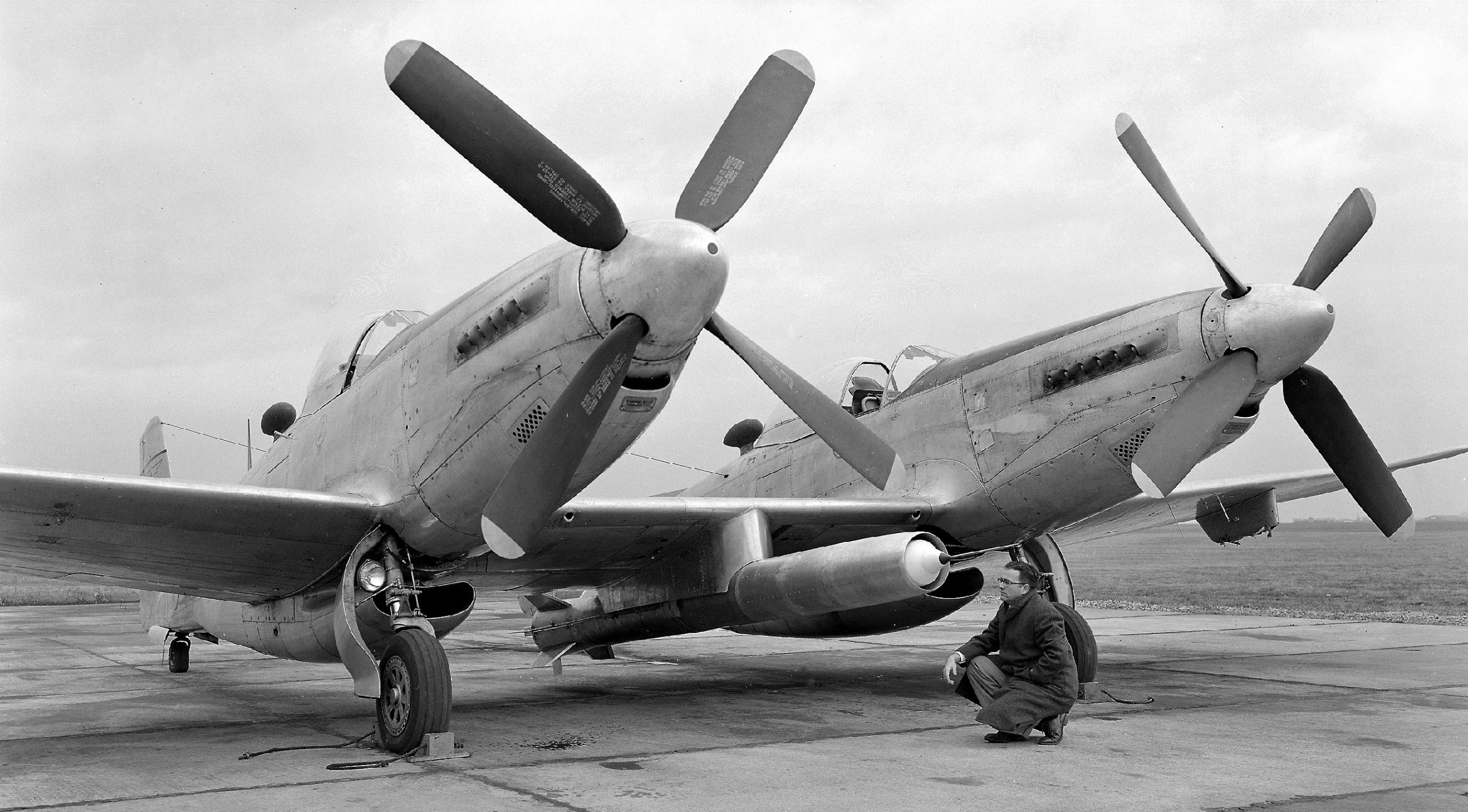
“The propellers are located side by side and 48 feet aft of the throat of the exit-cone bell. The propellers are 35 feet 5 inches in diameter and each consists of four cast aluminum alloy blades screwed into a cast steel hub….. …..The most commonly used power plant for operating a wind tunnel is a direct-current motor and motor-generator set with Ward Leonard control system. For the FST it was found that alternating current slip-ring induction motors, together with satisfactory control equipment, could be purchased for approximately 30 percent less than the direct-current equipment. Two 4,000-horsepower slip-ring induction motors with 24 steps of speed between 75 and 300 r.p.m. were therefore installed. In order to obtain the range of speed one pole change was provided and the other variations are obtained by the introduction of resistance in the rotor circuit. This control permits a variation in air speed from 25 to 118 miles per hour. The two motors are connected through an automatic switchboard to one drum-type controller located in the test chamber. All the control equipment is interlocked and connected through time-limit relays, so that regardless of how fast the controller handle is moved the motors will increase in speed at regular intervals.”-Smith DeFrance, NACA TR #459 pages 294-295

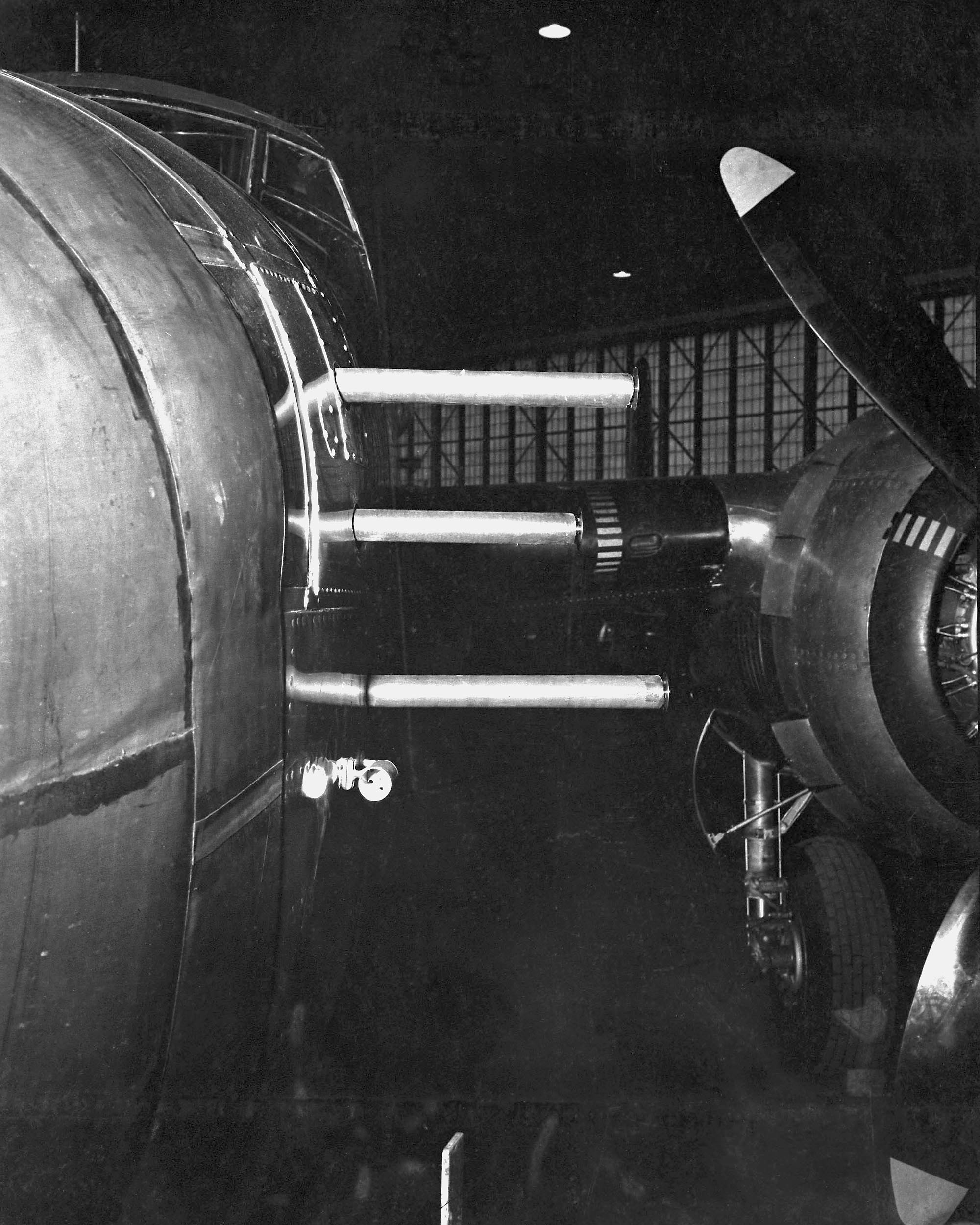
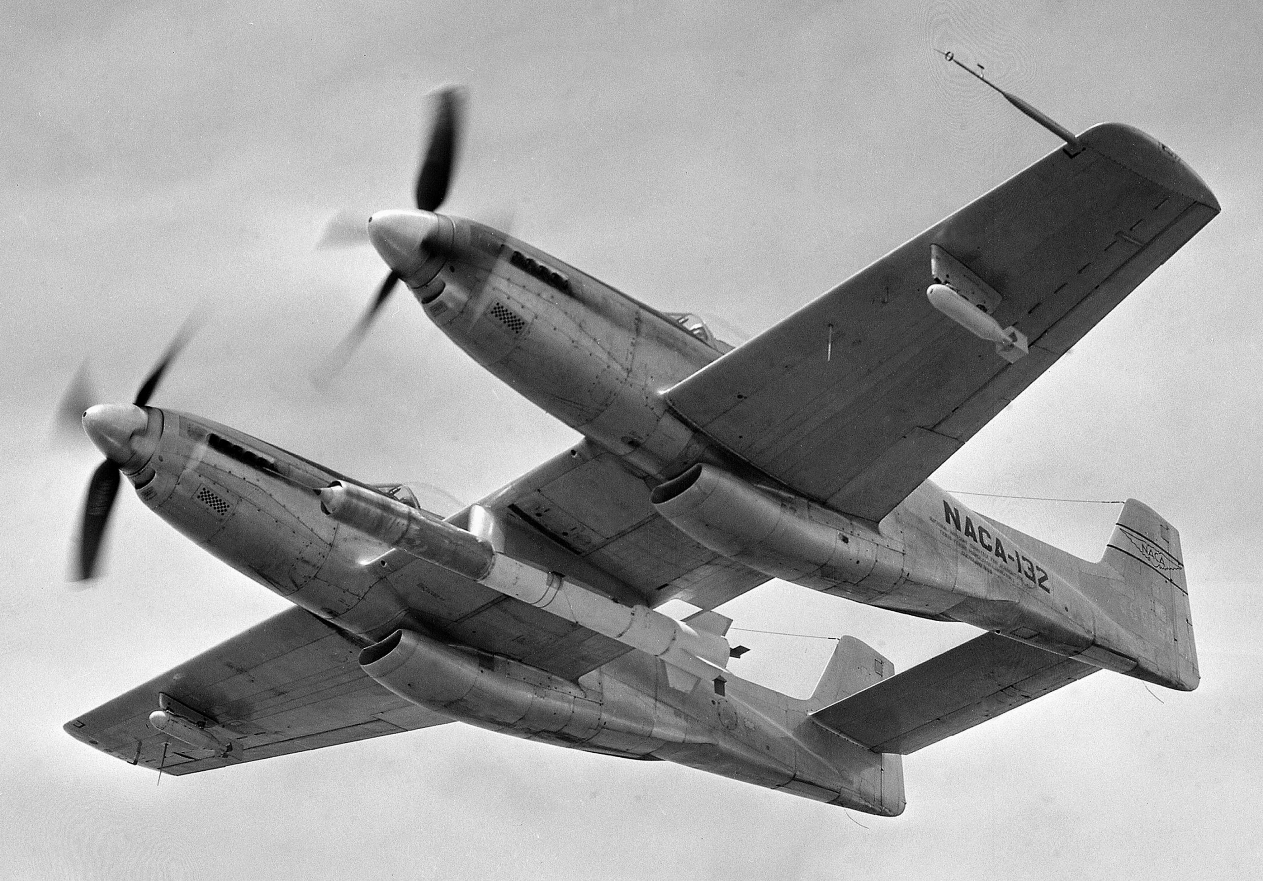
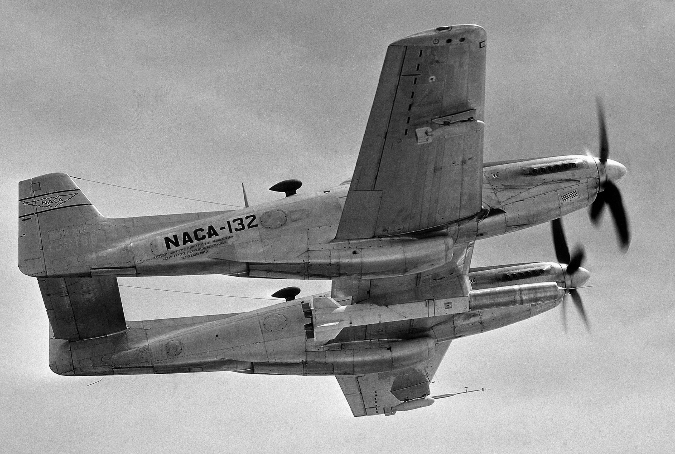
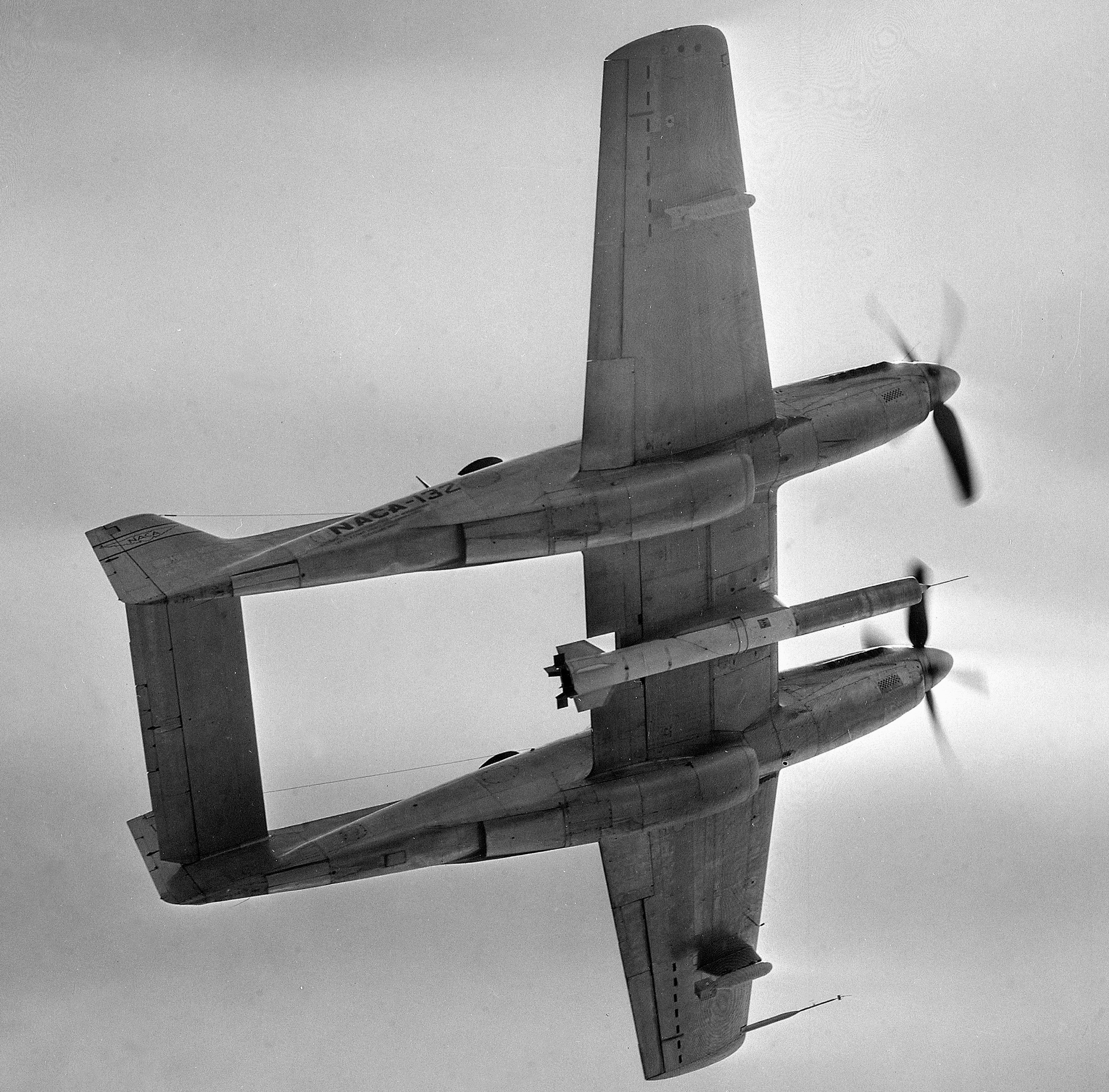
The above photo shows the twin tunnel funnel with diesel motors before the giant propellers were mounted. This ‘cone’ sucked the air out.

Entrance cone, where the air came into the wind tunnel room.

Even though the wind was generated by diesel powered props, the Full Scale Wind Tunnel still required electricity from “Two 4000-horsepower slip-ring induction motors with 24 steps of speed between 75 and 300 r.p.m….”

The completed building housing the Full Scale Wind Tunnel, also known as the 30×60 Tunnel: “The entire equipment is housed in a structure, the outside walls of which serve as the outer walls of the return passages. The over-all length of the tunnel is 434 feet 6 inches, the width 222 feet, and the maximum height 97 feet. The framework is of structural steel….”-NACA TR #459 pages 292-293


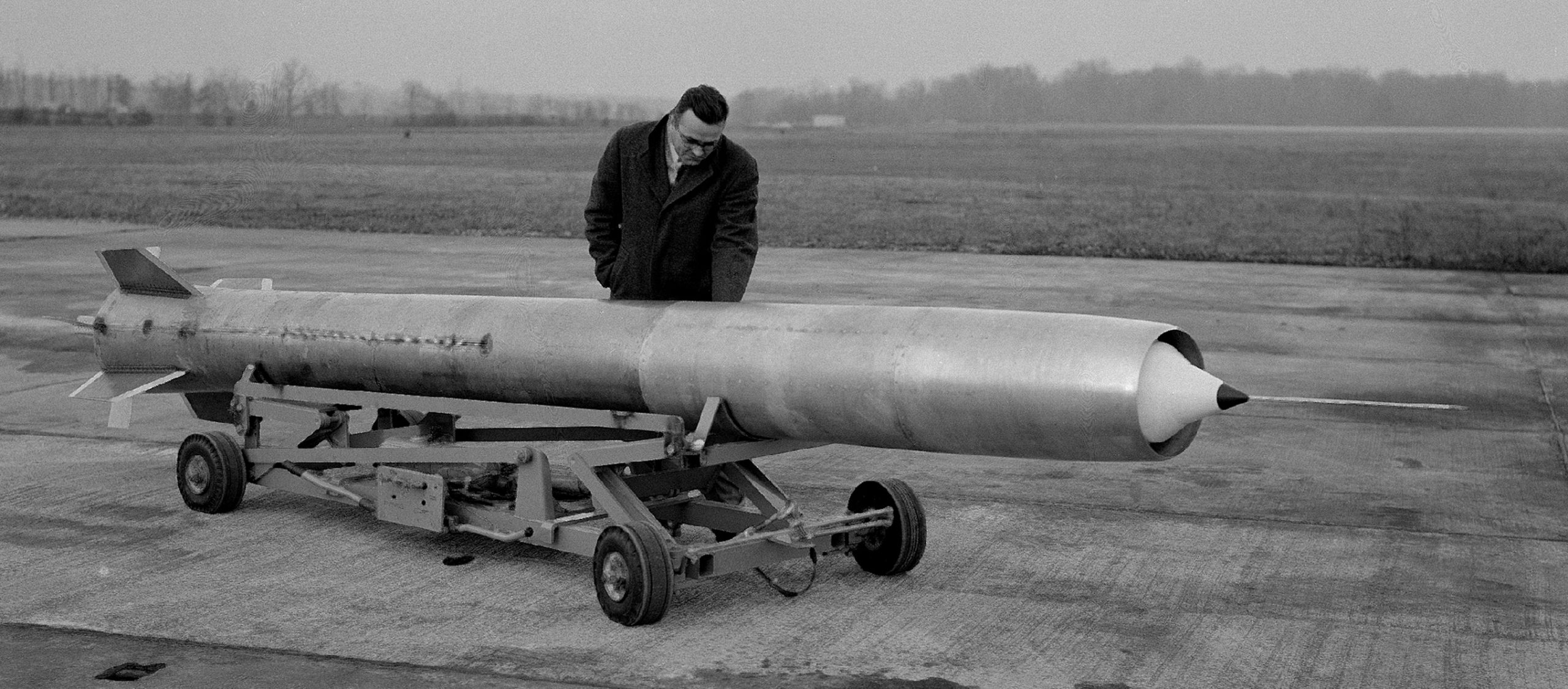
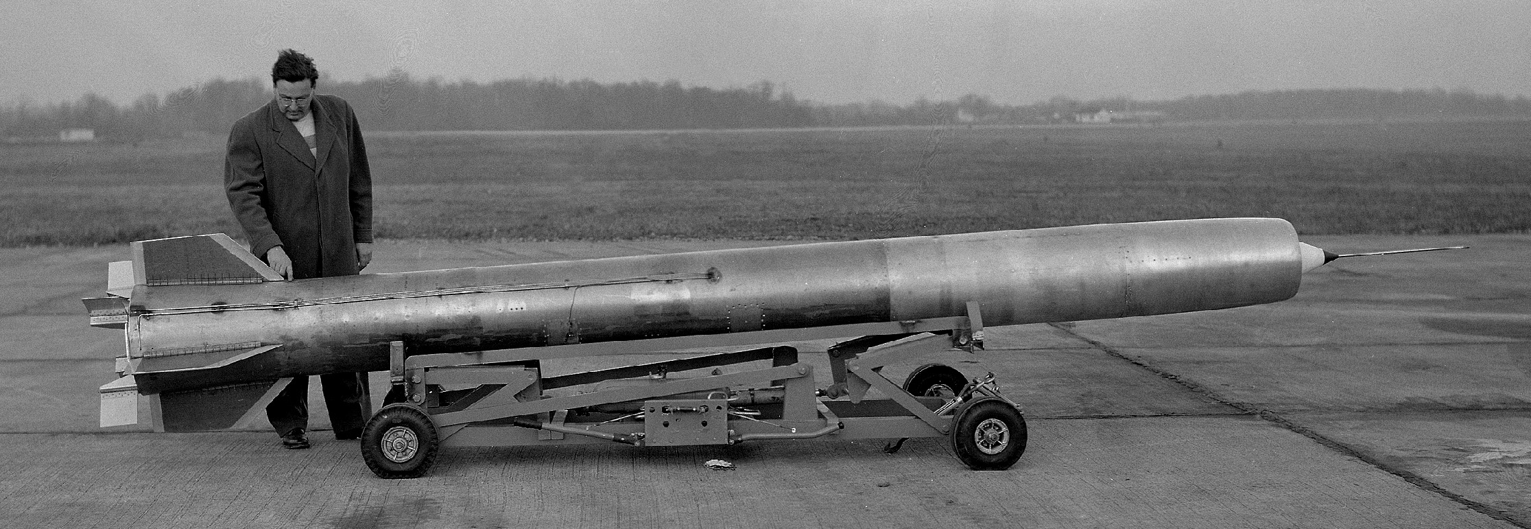
Testing nacelles for the U.S. Navy.

Vought SU-2 Corsair/O3U-4 in Langley’s Full Scale Wind Tunnel in 1934. The cowling around the engine is the less aerodynamic Townend cowling.


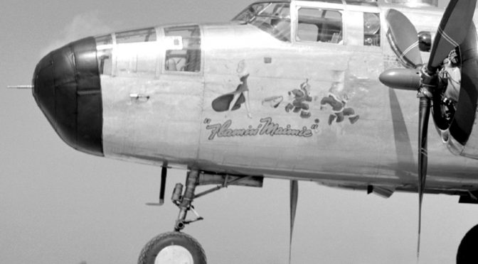
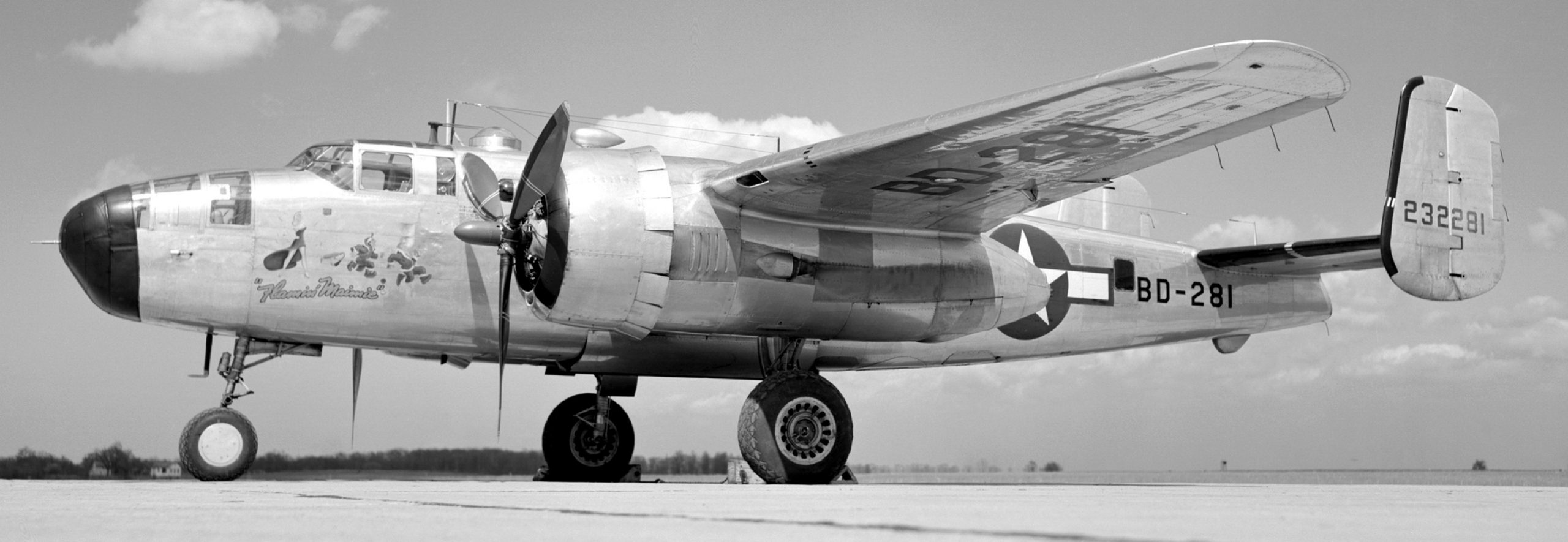
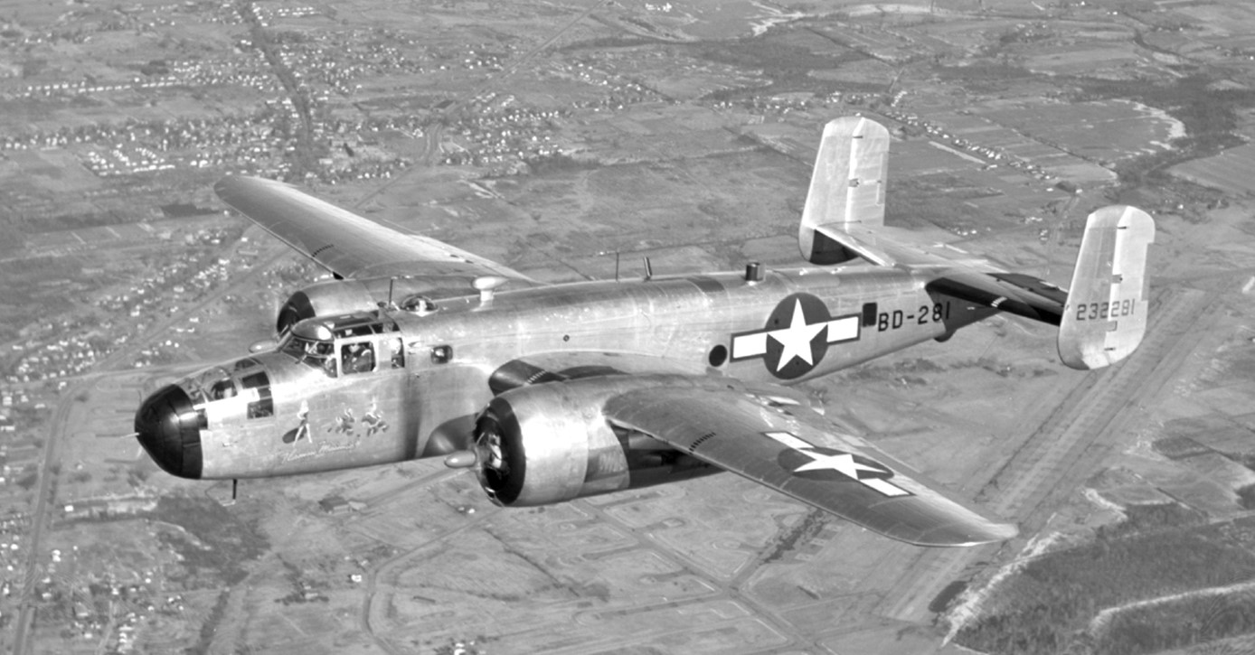
Testing of the lowly Brewster Buffalo was so successful in discovering aerodynamic inefficiencies that the U.S. Army and Navy sent most of their World War Two prototype and production aircraft to the Full Scale Wind Tunnel for similar examination.

Vought F4U-1 Corsair: This production F4U-1 underwent wind tunnel trials in an effort to find potential aerodynamic refinements.
 MX-334 flying wing glider, 1943.
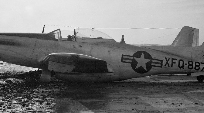
 Bell XP-77 1:1 scale model, 1943.
The 30×60/Full Scale Wind Tunnel has undergone numerous upgrades since World War Two.
 Mercury space capsule, January 1959.
 Testing the proposed parawing landing system for space capsules.


 Testing one of the proposed Lunar Excursion Module (LEM) models.


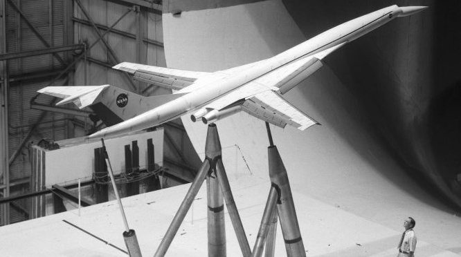
The scale model built to test the swept-wings of the Super Sonic Transport (SST) was so big the Full Scale Wind Tunnel had to be used.

 In 1999, NASA (National Aeronautics Space Administration) decided to test a 1:1 scale model of the Wright Flyer, for aerodynamic data. However, the full-scale Wright Flyer was built stronger than the original for fear it wouldn’t hold up in the wind tunnel (it was tested at only 30mph/48kmh).
Despite being declared a National Historic Landmark, demolition of the 30×60 Full Scale Wind Tunnel began in 2010, officially declared dead and buried in 2014.
VEHICLE I-D: NASA CANBERRAS, B-57B ‘HUSH KIT’ & WB-57F RIVET CHIP/SLICE
BARE METAL: NASA’S MD-11 EXPERIMENTAL
IDAHO, KANSAS, UTAH HOME BASES FOR NASA’S DC-8 FIREX-AQ!
NASA ‘CLIMATE SPY PLANE’ PROVES CALIFORNIA’S STRICT ANTI-POLLUTION LAWS ARE A JOKE!
SUPER GUPPY BE OLD, BUT NASA STILL USES IT!
VEHICLE I-D: ‘NEW’ F-16 VISTA
VEHICLE I-D: F-8 DFBW, OR ANOTHER REASON WHY TODAY’S TECHIE GENERATION OWES THE MILITARY INDUSTRIAL COMPLEX!
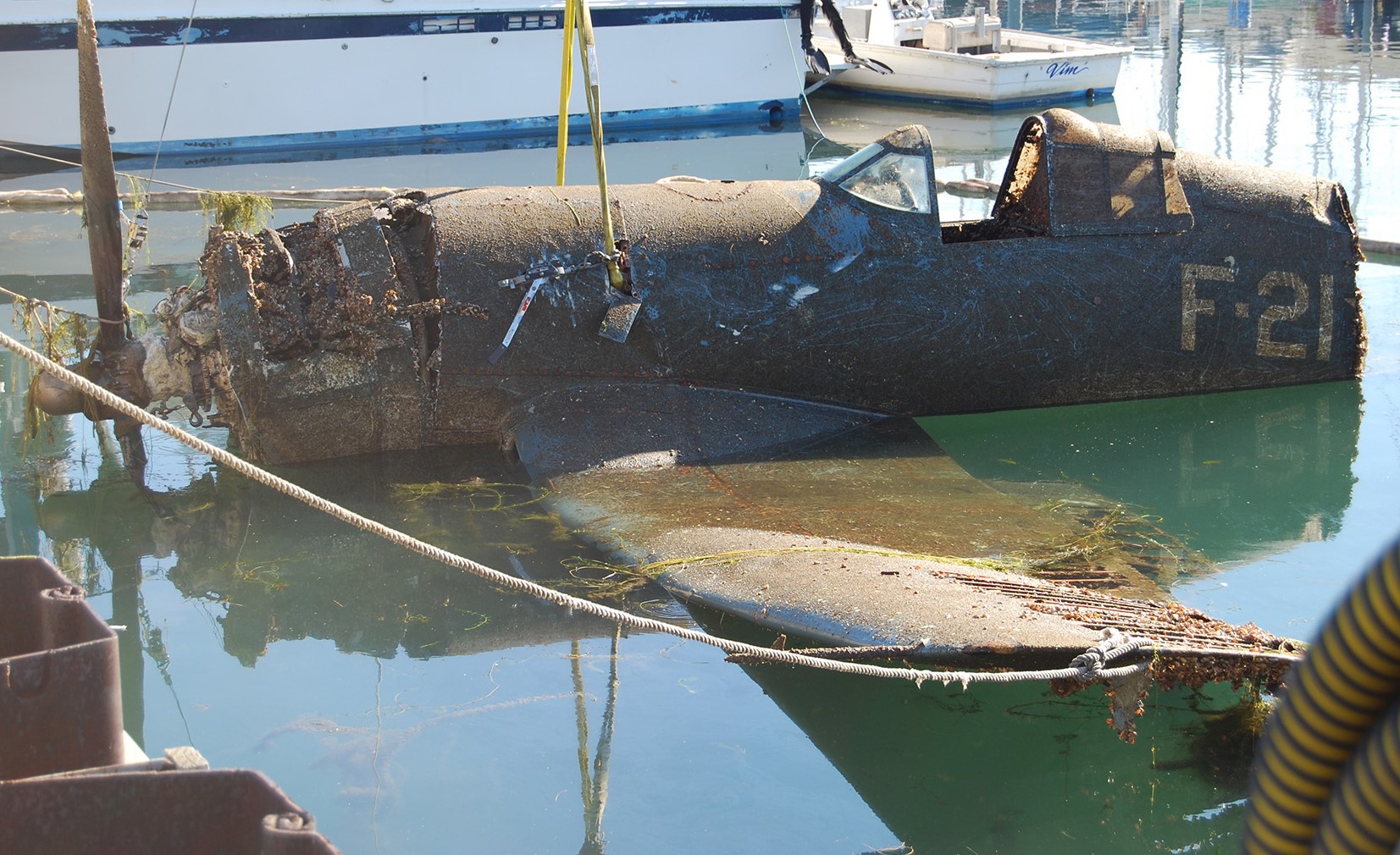
SALVAGING F4U CORSAIRS
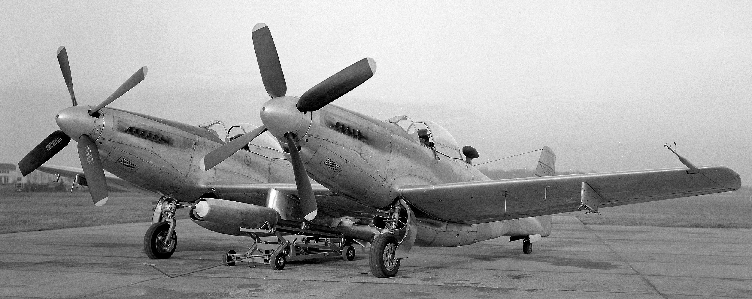
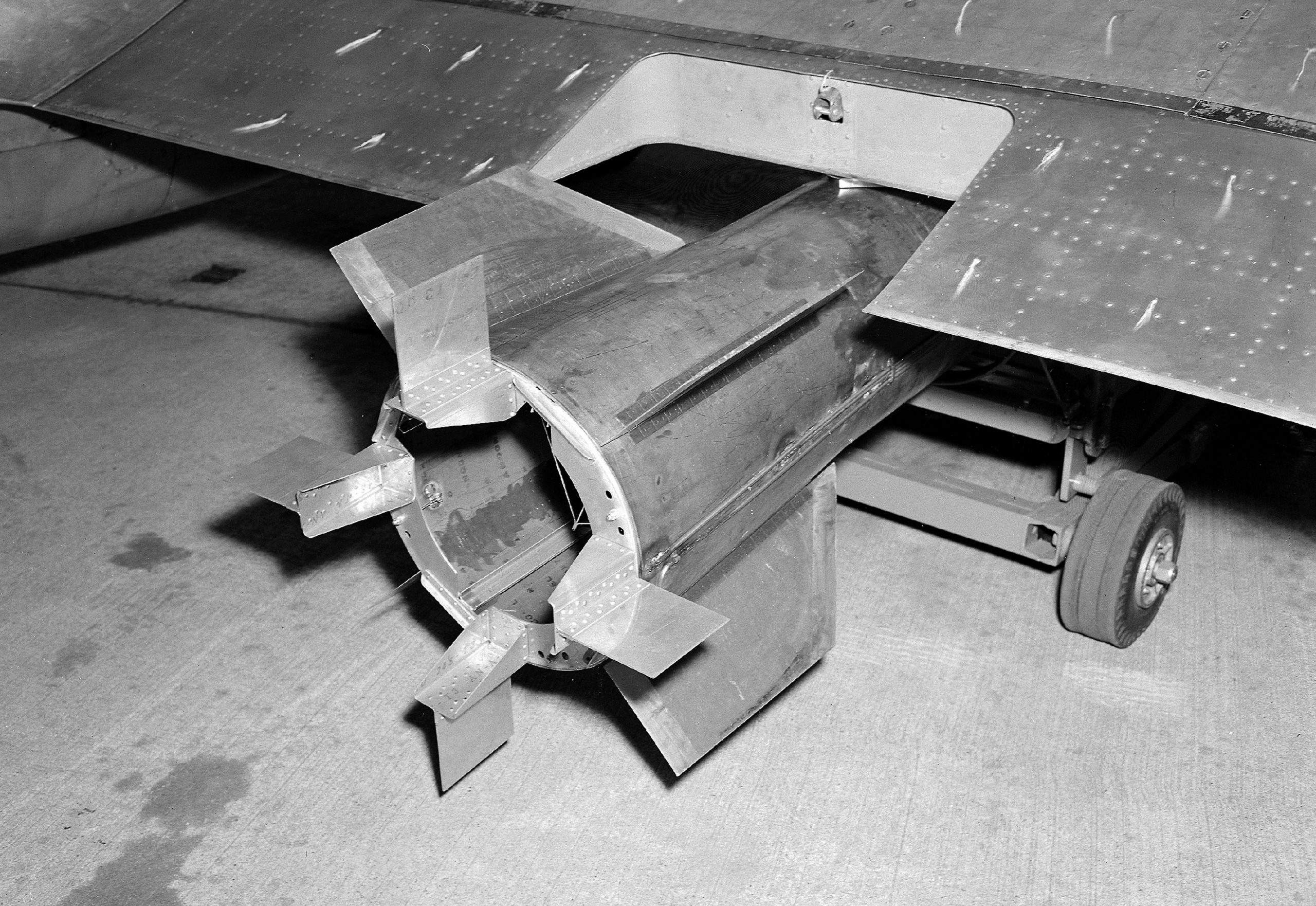
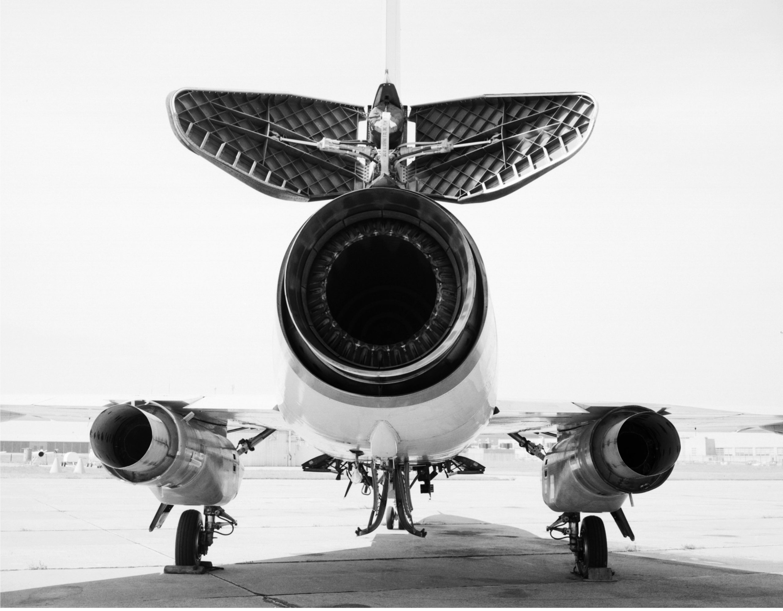 TRIPLE ENGINED F-106B DELTA DART; MORE TAXPAYER FUNDED SUPPORT FOR THE AIRLINER INDUSTRY